
Instruction Manual


9-22
All Rights Reserved. Copyright © 2003, Rota Yokogawa
IM 01R04B04-00E-E 8th edition March 01, 2011 -00
WARNING
1. Ex type RCCF31 and RCCS3 must be connected to the suitable IS earthing system (see installation
diagram). Converter and detector case must have connection to the potential equalisation facility.
2. Use the certied cable glands, suitable for the conditions of use.
3. Please conrm that the ground terminal (inside the terminal enclosure) is rmly
connected by means of a clip-on eye-let.
4. For EMC technical reasons the case of the detector is connected to the case of the converter via the
shielding of the interconnecting cable.
Cable glands for power- and I/O-cables :
RCCF31-xxxM : Ex e types are enclosed. These cable glands can also be used for “dust application” tD.
Use IECEx- certied Ex d cable glands for Ex d condition.
RCCF31-xxxA : No cable glands are enclosed. Use the IECEx- certied cable glands, suitable for the
conditions of use (Ex de or Ex d or tD)
For “dust application” tD use cable glands with minimum IP67 protection !
Cable glands for detector connection terminal :
RCCF31-xxxM : Cable glands are tted in the concerning thread. This cable gland can also be used for
“dust application” tD.
RCCF31-xxxA : Cable glands are enclosed. This cable gland can also be used for dust application” tD
.
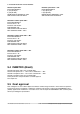
L/+
N/-
G
Power supply
I/O control
Hazardous area Safe area
I/O
Rotamass RCCT3
F91.EPS
Terminal Box
Detailed information for connection intrinsic safe outputs (option /EF2 see chapter 4.4.5.
Installation diagram (option /EF1) :
WARNING
1. Ex type of ROTAMASS must be connected to the suitable IS earthing system (see installation
diagram). Converter case must have connection to the potential equalisation facility. If the
connecting process tubing is part of the potential equalisation, no additional connection is required.
2. Use the certied cable glands, suitable for the conditions of use. The delivered cable glands are only for
Ex e use. For Ex d use certied d-type cable glands.
3. Please conrm that the ground terminal (inside the terminal enclosure) is rmly connected by means of
a clip-on eye-let.
4. Ex-e terminals for power supply and I/O-lines are designed for cables with cross section of 0.08 mm²
(AWG 28) to 2.5 mm² (AWG 22). The strip length must be 5 to 6 mm (0.2 to 0.24 in).
Cable glands for power- and I/O-cables :
RCCT3x-xxxM : Ex e types are enclosed. These cable glands can also be used for “dust application” tD.
Use IECEx- certied Ex d cable glands for Ex d condition.
RCCT3x-xxxA : No cable glands are enclosed. Use the IECEx- certied cable glands, suitable for the
conditions of use (Ex de or Ex d or tD).
For “dust application” tD use cable glands with minimum IP67 protection !