
Instruction Manual


9-11
All Rights Reserved. Copyright © 2003, Rota Yokogawa
IM 01R04B04-00E-E 8th edition March 01, 2011 -00
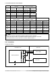
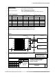
Remote eld-mount type RCCF31 with RCCS3 :
L/+
N/-
G
Power supply
I/O control
Hazardous area Safe area
I/O
RCCF31
RCCS3
D+
D-
S1+
S1-
S2+
S2-
TP1
TP2
TP3
D+
D-
S1+
S1-
S2+
S2-
TP1
TP2
TP3
COM
Exclusive remote cable RCCY03
F92.EPS
Terminal Box
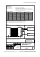
- The owmeter must be connected to the potential equalization system. For remote
type converter and detector case must have connection to the potential equalisation
facility.
- For remote type at ambient temperature up to 60°C / 140°F use remote cable RCCY031 or RCCY032.
- For remote type at ambient temperature up to 80°C / 176°F use remote cable RCCY033.
- Maximum length of remote cable is 50 m/164 ft.
- Specied maximum ambient temperature of cables (power supply-, I/O- and remote cable) must be
20°C / 41°F above maximum ambient temperature of owmeter.
- For AC-version maximum power supply is 250 V AC.
- Install according National Electrical Code. Intrinsically safe circuits must be installed according NEC ANSI
/ NPFA 70 amd ISA RP 12.6.
- Use certied XP (explosion proof) cable glands for power supply and I/O.
- Please conrm that the ground terminal (inside the terminal enclosure) is rmly connected by means of a
clip-on eye-let.
- For EMC technical reasons the case of the detector is connected to the case of the converter via the
shielding of the interconnecting cable.
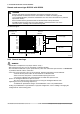
CAUTION
- Remove the stopping plug on detector connecting side and replace it by a dust proofed cable gland.
- Open the cover on detector connecting side of RCCF31.
- Remove the cable between COM- terminal and the ground screw.
- Put the intrinsic safe ground cable through the new installed cable gland.
- Connect the IS-ground cable to the COM- terminal.
- Install the remote cable between detector RCCS3 and converter RCCF31 as shown in this chapter.