User's Manual 3 Series Coriolis Mass Flow and Density Meter Integral Type RCCT3 Remote Type RCCF31 + RCCS3 Remote Type RCCR31 + RCCS3 IM 01R04B04-00E-E Rota Yokogawa GmbH & Co. KG Rheinstr.
Blank Page
CONTENTS Contents 1. Introduction....................................................................................1-1 1.1 Using the Coriolis Flowmeter Safely.............................................................1-2 1.2 Warranty...........................................................................................................1-3 1.3 Instruction according EMC.............................................................................1-3 1.4 ATEX Documentation...............................
CONTENTS 4. Installation.....................................................................................4-1 4.1 General ........................................................................................................................................... 4-1 4.2 Mounting of detector RCCS30 to 33 option /PD................................................4-2 4.3 Piping................................................................................................................4-2 4.
CONTENTS 6. Operation via HART........................................................................6-1 6.1 Conditions of communication line................................................................6-1 6.2 Communication via FieldMate........................................................................6-2 6.3 Communication via HART Communicator....................................................6-5 6.4 Unique functions of HART Communicator...................................................6-6 6.
CONTENTS 7.22 Corrosion detection (Detailed Setup)......................................................7-102 7.23 Detector data (Detailed Setup).................................................................7-102 7.24 Autozero (Diag/Service)............................................................................7-103 7.25 Reading maximum fluid temperature (Detailed Setup).........................7-104 7.26 Option /GA for Gas Measurement...........................................................
CONTENTS 9. Explosion protected type instruments................................ 9-1 9.1 ATEX.................................................................................................................9-1 9.1.1 Technical Data...................................................................................................... 9-1 9.1.2 Installation............................................................................................................. 9-4 9.1.3 Operation...........................
CONTENTS APPENDIX 2. Safety Instrumented Systems Installation.................. A2-1 A2.1 Scope and Purpose................................................................................... A2-1 A2.2 Using Rotamass 3 for a SIS Application................................................. A2-1 A2.2.1 Safety Function................................................................................................A2-1 A2.2.2 Safety Accuracy........................................................................
1. INTRODUCTION 1. Introduction Safety and Modification Precautions • The following general safety precautions must be observed during all phases of operation, service, and repair of this instrument. Failure to comply with these precautions or with specific WARNINGS given elsewhere in this manual violates safety standards of design, manufacture, and intended use of the instrument. Yokogawa assumes no liability for the customer's failure to comply with these requirements.
1. INTRODUCTION Protective grounding terminal (3) Operation • Do not open the cover until the power has been off for at least 10 minutes. Only expert engineer or skilled personnel are permitted to open the cover. (4) Maintenance • Maintenance on the Coriolis flowmeter should be performed by expert engineer or skilled personnel. No operator shall be permitted to perform any operations relating to maintenance. • Always conform to maintenance procedures outlined in this manual.
1. INTRODUCTION 1.2 Warranty Restriction on Use of Radio Transceiver : IMPORTANT • The warranty terms of this instrument that are guaranteed are described in the quotation. We will make any repairs that may become necessary during the guaranteed term free of charge. • Please contact our sales office if this instrument requires repair. • If the instrument is faulty, contact us with complete details about the problem and the length of time it has been faulty, and state the model and serial number.
1. INTRODUCTION 1.4 ATEX Documentation This is only applicable to the countries in European Union. GB SK CZ DK I LT E LV EST NL PL SF SLO P H F BG D RO S M GR IM 01R04B04-00E-E 8th edition March 01, 2011 -00 1-4 All Rights Reserved.
1. INTRODUCTION 1.5 Disposal, Cleaning and Return the failure occurred. It will be helpful if schematic diagrams and/or records of data are attached to the failed instrument. Whether or not the failed instrument should be repaired free of charge shall be left solely to the discretion of the Seller as a result of an inspection by the Seller.
1. INTRODUCTION Receiver : Sender : Delivery Note (for EU-Countries) Date : Ref. REPAIR for serial no.
1. INTRODUCTION Receiver : Sender : PROFORMA INVOICE (for Third-party-Countries) Date : Ref. REPAIR for serial no.
1. INTRODUCTION 1.6 Confirmation of accessories When you received the instrument, please check the following accessories.
2. Transportation and storage 2. Transportation and Storage Transport instructions When transporting the instrument, you must observe the following safety instructions in order to avoid lethal injury, damage to the instrument and other material damage. The steps involved in transport may only be carried out by qualified persons taking into account the safety instructions. • • • • • • • • Observe the transport instructions on the packaging. Observe the below mentioned storage conditions.
2. Transportation and storage Blank Page IM 01R04B04-00E-E 8th edition March 01, 2011 -00 2-2 All Rights Reserved.
3. Product description 3. Product description 3.1 The functional principle The ROTAMASS instrument measures the mass flow with the help of the so-called Coriolis force. This force occurs, when the medium being measured is flowing at velocity ν through a tube that is rotating around an axis perpendicular to the direction of flow at angular velocity ϖ. When the medium moves away from the axis of rotation it must be accelerated to an increasingly high peripheral velocity.
3. Product description 3.2 The Integral Type RCCT34 to 39/IR The following drawing shows the general construction of the integral type ROTAMASS Display Terminal box power and I/O Power supply cable entry I/O - line cable entry Name plate Flow direction arrow Detector assembly F31.EPS 3.3 The Remote Field-Mount Converter RCCF31 The following drawing shows the general construction of the remote field-mount converter.
3. Product description 3.4 The Remote Rack-Mount Converter RCCR31 The following drawing shows the general construction of the remote rack-mount converter. Terminal board 19-inch cassette Input / Output terminals D+ DS1+ S1S2+ S2TP1 TP2 TP3 COM PE Detector connection terminals PE Iout1+ Iout1Iout2+ Iout2Pout+ PoutSin+ SinSout+ SoutL/+ N/G Ground terminals Display and infrared switches All Rights Reserved. Copyright © 2003, Rota Yokogawa 3-3 IM 01R04B04-00E-E Power terminals F35.
3. Product description 3.5 The Remote Detector RCCS30 to 33 The following drawing shows the general construction of the remote detector RCCS30 to 33. Name plate Terminal box 3.6 The Remote Detector RCCS30 to 33 /Tx The following drawing shows the general construction of the remote detector RCCS30 to 33 /Tx. see table 8 Factory insulation Terminal box Process connection Heating connection Name plate Ventilation optional /T3 F37.
3. Product description 3.7 The Remote Detector RCCS34 to 39/IR The following drawing shows the general construction of the remote detector RCCS34 to 39/IR. Terminal box Option /S2 and /MT F34.EPS All Rights Reserved.
3. Product description 3.8 The Remote Detector RCCS34 to 39/IR /Tx The following drawing shows the general construction of the remote detector RCCS34 to 39/IR /Tx. Heating connection optional /T2 or /T3 Process connection Factory insulation Terminal box Ventilation optional /T3 F36.EPS IM 01R04B04-00E-E 8th edition March 01, 2011 -00 3-6 All Rights Reserved.
3. Product description 3.9 The Remote and Integral Type RCCx39/XR The following drawing shows the general construction of the RCCx39/XR. Remote Type RCCS39/XR Terminal box Option /S2 and /MT Integral Type RCCT39/XR F38.EPS All Rights Reserved.
3. Product description 3.10 Measurement system and applications ROTAMASS measures the mass flow of fluids directly. The measurement system uses the Coriolis principle and is suitable for a wide range of continuous flow measurement applications in all branches of process technology. ROTAMASS has two components: the detector and the converter. The detector measures the mass flow directly and converts it into electrical signals.
3. Product description 3.
3. Product description Name plate of Remote Detector RCCS3: 1 2 3 4 5 6 7 8 9 10 11 Model code Serial number Calibration constants of detector (see also on calibration certificate) Number of notified body according ATEX (only for ATEX certified flowmeters) Number of notified body according PED (only for units with process connections greater than DN25) Area for Ex- relevant marking (see chapter 9). The CE-mark is not present for FM-approved units.
4. INSTALLATION 4. Installation 4.1 General WARNING This instrument must be installed by an expert engineer or skilled personal. The procedures described in this chapter are not permitted for operators. For the installation of explosion protected instruments see chapter 9 „Explosion protected type instruments”. If the detector is not insulated, the surface of detector may be very hot according to the process temperature.
4. INSTALLATION 4.2 Mounting of detector RCCS30 to 33 option /PD The detector RCCS30 to 33 can be mounted on a 2-inch pipe (option /PD) with a bracket and U-bolt assy. 4.3 Piping IMPORTANT When the following notes are not observed, flow measurements may not be correct and can damage the instrument. Please make correct piping design in accordance with the present guidelines.
4. INSTALLATION Vertical installation (recommended): Makes pipe easier to empty (in case of maintenance, startup, product change). Helps gas bubbles to escape. Only one shut-off valve is required to ensure “no flow” for setting Autozero. Flow Horizontal installation : For liquids: Measuring tube downwards so that no gas can collect if “no flow”. For gasses: Measuring tube upwards so that no liquid can collect if “no flow”.
4. INSTALLATION (pipe) (detector) (pipe) (pipe) Please avoid direct fixing at detector. This causes measurement errors. (detector) (pipe) Please use the piping to support the detector. In addition, to secure the support of only one side of the pipe detector. F0302.ai IMPORTANT When density measurement is used and the instrument is set up horizontally, you will need to set a predetermined correction factor into the converter. Please see chapter 7.7.
4. INSTALLATION 1JQF GMBOHF (BTLFU 'MPXNFUFS 'MBOHF /VU #PMU ' BJ (3) Mounting Clamp Clamp and gasket must be mounted to fit into the groove of the ferrules of the pipe, fitted to cover the taper portion of the ferrule to the Coriolis flowmeter. The ferrules, clamps, gaskets are not included and must be provided on site. Clamp Gasket Ferrule F0306.ai Gas flow measurement CAUTION A stable zero is mandatory for a good mass flow measurement.
4. INSTALLATION 4.4 Customer insulation Customer insulation is only possible for remote detector RCCS3x with option /S2 (terminal box on distance). The upper line of the insulation must be minimum 40 mm below the terminal box. IMPORTANT For explosion proof types see tables "Temperature classification" in chapter 9. 4.5 Mounting of converter RCCF31 to 2-inch pipe The field-mount converter RCCF31 can be mounted on a 2-inch pipe. Therefore use the delivered bracket and U-bolt assy. F0309.
4. INSTALLATION 4.6 Mounting of converter RCCR31 in a subrack If the remote rack mount converter RCCR31 was not ordered with option /SR1 or /SR2, the customer has to mount it to an own 19´´ subrack. The terminal board must be fixed by 6 screws (M2.5x10) to the rear side of the subrack. The RCCR31 rack cassette must be inserted into the subrack. 4.7 Alteration of display (RCCT3 / RCCF31) LCD display can be turned its direction with respect to piping configurations.
4. INSTALLATION 4.8 Wiring 4.8.1 General items Notes concerning the wiring When wiring, please observe the following precautions. WARNING - In order to prevent damage from condensation ensure isolation of the terminal box of the Coriolis flowmeter. - Conduit wiring is recommended. Please use wiring conduit thick steel or flexible. In �������������������� order to prevent rainwater from flowing or remain into the wiring pipe, please keep the watertight using a seal tape.
4. INSTALLATION Wiring port handling (1) When waterproof property is unnecessary For meters with NPT 1/2´´ threads the wiring port is sealed with a cap (not water-proof) that must be removed before wiring. For the unused wiring port, please prepare plug by the customer. For explosion proof, please refer to Chapter 9.
4. INSTALLATION 4.8.2 Ground (earth) connections IMPORTANT Grounding resistance of 10 Ω or less is necessary. For explosion proof type follow the domestic electrical requirements as regulated in each country.
4. INSTALLATION 4.8.3 Wiring technique Cable connection on terminal block: For connecting the cables to power-, I/O- and remote cable connection terminals a special tool is attached to the instrument. The terminal looks as follows: $BCMF DPOOFDUJPO QPSU 8JSJOH UPPM TMPU $BCMF PP $BCMF DPOOFDUJPO QPSU D+ D– 8JSJOH UPPM TMPU S1+ S1– S2+ S2– TP1 TP2 TP3 COM YOKOGAWA ' BJ Insert the auxiliary tool from the top into the terminal block.
4. INSTALLATION 4.8.4 Assembling and connecting the Remote Cable RCCY03 Remote type converter RCCF31 / RCCR31 are used with remote type detector RCCS3. To connect these instruments use pair- / triple-twisted cable with overall shielding type Li2Y(st)+CY 3x2AWG24 + 1x3 AWG20 exclusive cable RCCY03.
4. INSTALLATION Termination procedure: Cable end detector - Remove PVC outer sheeting and outer shielding 100 mm from the end. - Remove the clear wrap and the filler material. - Remove the foil that is around the isolated wires. - Clip off each drain wire close to the cable jacket. - Slide a shrink down plastic tube (d = 3.2 mm, l = 20 mm) over each of the 3 pairs and a shrink down plastic tube (d = 4.8 mm, l = 20 mm) over the triple of wires, push it to the cable jacket and heat with hot air.
4. INSTALLATION Cable connection to detector RCCS3 and field-mount converter RCCF31: 1. Remove connection box cover detector and converter (see figure below). ' BJ 2. ���������������������������������������������������������������������������������������������������������� Loosen the thread of cable gland and insert the cable into the cap and the clamp part. ������������������� (See figure below.) 3.
4. INSTALLATION Cable connection to rack-mount converter RCCR31: 1. Loose the cable clamp on terminal board 2. Remove the 25 mm section of PVC outer sheathing from the cable and fix the outer ring of the cable with the cable clamp on terminal board. (see left figure below). 3. Connect the numbered leads to the terminals as shown in the right figure below. 4. Connect inner shields to terminal COM.
4. INSTALLATION CAUTION 1. Before starting the wiring, turn off the source of the supply power and check with the tester that there is no voltage at the cable. 2. For RCCT3 / RCCF31 the protective ground conductor must be connected to the separate PE terminal in the terminal box with Crimp-on ring-type terminal in order to avoid personal shock hazard. 2. For RCCR31 the protective ground conductor must be connected to the separate PE terminal on the terminal board in order to avoid personal shock hazard.
4. INSTALLATION CAUTION Special connections for Ex version : The converter case must be connected to the potential equalisation facility of the hazardous area , e.g. to the U-clamp PA terminal on the outside at the converter. Please refer to chapter 9 “Explosion Protected Type Instruments”. Power supply cable Cable : Use cables acc. to VDE 0250, Outer diameter : DIN and NPT cable gland: 6.
4. INSTALLATION 4.8.6 Connecting to external instruments • Use cables with cross section 0.08 to 0.5 mm² • Connect the cables from the external instruments to the terminals inside of the converter terminal box (RCCT3 / RCCF31 or on terminal board (RCCR31). • Confirm two ferrite core sets are attached to the flowmeter. • Insert the cable into ferrite core before connecting to the terminals. Fix the ferrite core (see figure on page 4-16) • Connect the cables to the terminals according to the figure below.
4. INSTALLATION 2. Pulse Output passive (Pout / Sout) ROTAMASS has 2 pulse outputs (isolated transistor contact). Attention must be paid to voltage and polarity when wiring (/KF2 has one passive pulse output, which is intrinsic safe. See chapter 4.8.8) Protective diode ROTAMASS Pout +/Sout + Mechanical counter Pulse output Pout - / Sout- ROTAMASS 30VDC, 200mA max Pout + /Sout + Load Pulse output Electronic counter Pout - / Sout- F412.EPS 3.
4. INSTALLATION 4. Pulse Output active (option /AP) Pulse output 1 (Pout) can be ordered as active output. Not possible with intrinsic safe outputs option /KF2. 305"."44 7 1VMTF SBUF: ∼ )[ ( L)[) Lų 1PVU *G UIF MPBE SFTJTUBODF JT Lų 7 7 WPMUBHF QVMTF JT PCUBJOFE &MFDUSPOJD DPVOUFS -PBE 1PVU ' BJ 5. Status Output active (option /AP) Status output 1 (Pout) can be ordered as active output. Not possible with intrinsic safe outputs option /KF2.
4. INSTALLATION 6. Pulse / Status Output according EN 60947-5-6 (NAMUR) (option /NM) Pulse output 1 (Pout) can be ordered as NAMUR output. Transmitter Relay ~ ROTAMASS 1k Pulse output Pout + ~ U + - 10k Pout F426.EPS 7. Status input (Sin) Status input is designed for use with voltage-free (“dry”) contact (activate source current to detect the contact state). Be careful not to connect to any signal source carrying any voltage. Applying voltage may damage the input circuit.
4. INSTALLATION 4.8.7 Connecting HART- Communication HART communication is available on analog output 1 and the HART-communicator is connected via load resistance (230 ... 600 Ω) as shown on the figure below. Control room 4 to 20mA DC signal transIntermediate mission line terminals Receiving instrument Terminal board ROTAMASS HART Communicator HART Communicator HART Communicator F417.EPS 4.8.
4. INSTALLATION Power supply range : 10.5 V … 30 V DC Power supply range : 16.75 V … 30 V DC Load resistance : 20 … 600 Ω Load resistance : 230 … 600 Ω Load resistance vs Power supply voltage : Load resistance [ Ω ] 800 700 600 500 400 300 200 100 0 10 for for for for Not-HART application HART application Not-HART application HART application HART communication available range 12 14 16 18 20 22 Power supply voltage [V] 24 26 28 30 F419.
4. INSTALLATION Blank Page IM 01R04B04-00E-E 8th edition March 01, 2011 -00 4-24 All Rights Reserved.
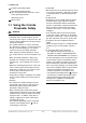
5. BASIC OPerating procedures 5. Basic operating procedures Data setting can be done by HART-Communication (see chapter 6) or with the 3 keys on the front panel. The following section describes how to use the three panel keys. IMPORTANT Operate the display unit under the condition where direct sunlight, etc.... do not shine to the setting switches directly when the parameter setting operation is carried out. NOTE (1) Always use the setting switches with the cover of the Rotamass closed.
5. BASIC OPerating procedures +123.450 +12.3400 0.99700 +12.3450 +123.450 + 12.3400 0.99700 l MFR TMP DEN FTL kg/h deg kg/l kg kg/h degC kg/l 4 line indication MFR 3 line indication TMP DEN +123.450 kg/h MFR +12.3400 degC TMP +123.450 MFR 2 line indication. 1 line indication kg/h F53.EPS NOTE The infrared switches operate as ON status by detecting the infrared ray reflection from a finger put over the switches through the glass plate of the cover.
5.
5. BASIC OPerating procedures 5.3 Setting via keys SHIFT SET The three keys , , are used to set parameters via display menu. The following flowchart shows how to reach the modes by using the keys : Chapter 7.2 shows the display parameter list and chapter 7.3 shows the parameter tree.
5. BASIC OPerating procedures 5.4 Examples of parameter settings via keys 5.4.1 Display configuration, set volume flow to line 1 SET 123.450 0.99700 12.3400 12.3450 MFR DEN TMP FTL kg/h kg/l degC kg Display config Display select 1 Display select 2 Display select 3 SET> 2s SET Setting Enable? Display select 1 Mass flowDisplay Mass flow Volume flow Density Temperature select F-Total flex R-Total flex D-Total flex ...........
5. BASIC OPerating procedures 5.4.2 Setting Temperature 20-120°C to Analog Output 2 SET 123.450 0.99700 12.3400 12.3450 kg/h kg/l degC kg MFR DEN TMP FTL Temperature Temperature unit Temperature LRV Temperature URV SET > 2s Temperature Temperature LRV Temperature URV Temperature damping Setting Enable? SET SET Temperature LRV 000.00 degC 000.00 degC Main Menu Language Process variables Diag/Service 3x Edit number with SHIFT and Temperature LRV 000.00 degC 020.
5. BASIC OPerating procedures SET Analog 2 select Density Temperature None Temperature URV 100.00 degC 000.00 degC 2x SET Edit number with SHIFT and Basic Setup Analog 2 select Pulse/Status out 1 Pulse/Status out 2 Temperature URV 100.00 degC 120.00 degC 2 x SHIFT + SET or SHIFT + SET > 3s 2x SET Temperature Temperature URV Temperature damping Temperature unit 123.450 0.99700 12.3400 12.3450 SHIFT + SET kg/h kg/l degC kg MFR DEN TMP FTL F57.
5. BASIC OPerating procedures 5.5 Setting parameters in converter with option /NC If remote converter RCCF31 / RCCR31 was ordered with option /NC (no combination), the customer must set the parameters of the connected detector by himself. In parameter Detailed Setup / Sensor model the sensor model must be selected.
5. BASIC OPerating procedures 5.6 Zero adjustment (Autozero) After the flow meter is installed into the process pipe work, set up the parameter corresponding to calibration certificate (generally set up in the factory) and perform the pre-operation zero adjustment. IMPORTANT Zero adjustment is required before beginning operation in order to obtain the output signals are accurately proportional to the flow. Zero adjustment is performed to set the instrument to 0% when the flow rate is 0.
5. BASIC OPerating procedures How to perform Autozero via keys : SET 123.450 0.99700 12.3400 12.
5. BASIC OPerating procedures After 30s /180s Autozero Auto zero Exe Auto zero Exe XXX .XXkg/h Execute Not Execute 2x SET After 3s Autozero Autozero Autozero exe Doing Autozero Date (DD/MM/YYYY) 00/00/2000 180sec Set date with SHIFT+ . Then press 2x SET � Autozero data are written in Autozero history. 3x SHIFT + SET � Measuring mode F58a.EPS Reading Autozero history (see also chapter 7.24) : 123.450 0.99700 12.3400 12.
5. BASIC OPerating procedures Blank Page IM 01R04B04-00E-E 8th edition March 01, 2011 -00 5-12 All Rights Reserved.
6. Operation viA HART 6. Operation via HART 6.1 Conditions of communication line A HART-communicator can communicate with the ROTAMASS RCCT_F3 from the control room, the ROTAMASS site or any other wiring termination point in the loop, provided there is a minimum load resistance of 230Ω between the connection and the instrument. To communicate, it must be connected in parallel with the ROTAMASS RCCT_F3, the connections are not polarized.
6. Operation viA HART 6.2 Communication via FieldMate FieldMate is a PC-based flexible field device management tool from Yokogawa. Features: - Instant device recognition upon connection for HART, FF, Profibus and BRAIN devices - Support of both FDT/DTM and EDDL technologies - Database support for offline maintenance - Full history and audit trail - Synchronization with PRM The segment viewer will automatically scan the bus and will list your devices.
6. Operation viA HART RCCT_F3 DTM: Start window All Rights Reserved.
6. Operation viA HART RCCT_F3 DTM: Process variables RCCT_F3 DTM: Device information IM 01R04B04-00E-E 8th edition March 01, 2011 -00 6-4 All Rights Reserved.
6. Operation viA HART 6.3 Communication via HART Communicator Keys and functions of HHT 375: HART communication terminals Hot key Touch screen display Navigation keys (4 arrow keys) Enter key Function key Tab key Alphanumeric keypad On/Off key The HART communicator automatically searches for ROTAMASS RCCT_F3 on the 4-20mA loop, when it is turned on. When HART communicator is connected to RCCT_F3, it displays the online menu. (If RCCT_F3 is not found, it displays “No device found. Press OK…”.
6. Operation viA HART The HART menu in chapter 7.4 shows the configuration of the online menu, which is needed for the operation with HART communicator. Select ´Device Setup´ to call up the desired item as follows: There are two choices to select the desired menu item: 1. Use the ↓ or ↑ key to select the desired item, and then press the → key. 2. Press the number key displayed for the desired item.
6. Operation viA HART While write protect status is released, enter a new password twice, within 30 sec in “New Password”. It will not be possible to set a new password when 10 minutes have elapsed. If a parameter, which is write enabled , is changed while the device is in “Enable wrt 10min”, release time is extended for further 10 minutes.
6. Operation viA HART 6.6 Hardware Write Protect If software write protection via password is not suitable to protect the access to the converter, a hardware write protection can be set: • Open the cover of the converter. • Unscrew the 4 screws of the display and move the display aside. • Set the jumper on JP1 of CPU-board as shown in the following picture. CPU Board JP1 Cable to display Enable Protect F64.
Mass flow unit Vol flow unit Density unit Temperature unit Velocity unit Mass flow (7.5) Volume flow (7.6) Density (7.7)) Temperature (7.8) Velocity (7.9) Analog Output 1 (7.10) Analog Output 2 (7.11) All Rights Reserved. Copyright © 2003, Rota Yokogawa 7-1 Zero adjustment (5.6) Net flow (7.19) Disp. contrast Input/ Output Test (8.4) Concentration measurement (7.18) Display select Self test/ status (8.3) Flow direction (7.
7. Parameter Description Differences between display and HART setting The Rotamass software is continuously improved. This leads to functions, which are different in HART (DD version 0401) and display setting (software version from 1.08.00) 7.2 Parameter list Parameter Write protect Data form Select Data range No Dec. point Unit - - R : read W : write Exe : execute R/W Reset Master Reset Power on Default - Yes Enable WRT 10 min Acc.
7. Parameter description Parameter Data form Data range mA as sel. Var. - 2 as sel. Var. 2 R : read W : write Exe : execute R - 2 Decimal - Status output 1 ASCII Pulse output 2 Decimal Status output 2 Analog output 1 mA Decimal - Analog output 2 Decimal - Analog output 2% Decimal Analog output 2 mA Decimal Pulse output 1 Dec.
7. Parameter Description Parameter Disp select 1 Data form Select Data range Mass flow Dec.
7. Parameter description Parameter Disp select 3 Data form Select Data range Mass flow Dec.
7. Parameter Description Parameter Disp contrast Data form Select Data range -5 Dec. point Unit - - R : read W : write Exe : execute R/W Reset Master Reset Power on Default - - R/W X 1.0 s - - R/W X Forward - - R/W X - - R/W X xxxx.XX X 0 -4 -3 -2 -1 0 1 2 3 4 5 Disp Period Select 0.5 s 1.0 s 2.
7. Parameter description Parameter Vol flow unit Data form Select Data range cm³/s Dec.
7. Parameter Description Parameter Data form Data range Dec. point Unit Vol flow LRV Decimal -Qvmax to Qvmax 0 to 5 Vol flow unit R : read W : write Exe : execute R/W Reset Master Reset Power on Default Vol flow URV Decimal -Qvmax to Qvmax 0 to 5 Vol flow unit R/W X Qvnom Vol flow damping Decimal 0 to 200 1 Sec.
7. Parameter description Parameter Temperature format Data form Select Data range xxxxxxx Dec. point - Unit - R : read W : write Exe : execute R/W Reset Master Reset Power on Default X xxxxxx.X Temperature unit R/W X -200 Temperature unit R/W X 230 xxxxx.X xxxx.XX xxx.XXX xx.XXXX x.XXXXX Temperature LRV Decimal Standard: -200 to 230°C 0 to 5 Temperature URV Decimal Temperature damping Decimal 0 to 200 1 Sec.
7. Parameter Description Parameter Analog 2 select Data form Select Data range Mass flow Dec. point Unit - - R : read W : write Exe : execute R/W Reset Master Reset Power on Default - - R/W X <3.6mA mA R/W X 3.8 (Namur); X Density Volume flow Density Temperature Concentration meas Net flow None Analog 2 alarm out Select <2.4mA <3.6mA 4.0mA >21mA >21.6mA Hold Measured Value Analog 2 low LMT Decimal NAMUR:3.8 to 20.5 mA 2 Not NAMUR:2.4 to 21.6 mA Analog 2 high LMT Decimal 2.
7. Parameter description Parameter Data form Data range Dec. point Unit R : read W : write Exe : execute Reset Master Reset Power on Default Pulse 1 rate Decimal 0 to 11000 Unit/ P 0 to 10000 Hz 0 to 5 0 Pulse 1 unit R/W X 1 kg/P Pulse 1 active mode Select On Active - - R/W X On Active - - R/W X 1ms - - R/W X 0P/Hz - - R/W X No function - - R/W X On Active - - R/W X Status out Off Active Pulse 1 width Select 0.05ms 0.1ms 0.
7. Parameter Description Parameter Pulse 2 select Data form Select Data range Mass flow Dec.
7. Parameter description Parameter SO 2 function Data form Select Data range No function Dec. point Unit - - R : read W : write Exe : execute R/W Reset Master Reset Power on Default - - R/W X On active - - R/W X Mass flow X No Function Flow-Direction Total switch Mass flow alm 1 Mass flow alm 2 Mass flow alm 1+2 Vol flow alm 1 Vol flow alm 2 Vol flow alm 1+2 Density alm 1 Density alm 2 Density alm 1+2 Temp alm 1 Temp alm 2 Temp alm 1+2 Concentr. meas alm 1 Concentr.
7. Parameter Description Parameter SV is Data form Select Data range Mass flow Dec.
7. Parameter description Parameter QV is Data form Select Data range Mass flow Dec.
7. Parameter Description Parameter Total flex unit Data form Select Data range g Dec.
7. Parameter description Parameter Data form Data range Dec.
7. Parameter Description Parameter Data form Concentration meas format Select Data range xxxxxxx Dec. point - Unit - R : read W : write Exe : execute R/W Reset Master X xxxxx.X X xxxx.XX X xxx.XXX X xx.XXXX X x.XXXXX Reset Power on Default xxxx.
7. Parameter description Parameter Net flow unit Data form Select Data range Dec.
7. Parameter Description Parameter Data form Data range Dec.
7. Parameter description 7.
7.
7.
7.
7. Parameter description Basic Setup Display contrast -5 Sel -4 -3 -2 -1 0 +1 +2 +3 +4 +5 Mass flow Mass flow unit g/s Sel g/min g/h kg/s kg/min kg/h kg/d t/min t/h t/d lb/s lb/min lb/h lb/d Density Mass flow LRV R/W Mass flow URV R/W Mass flow damping R/W Density unit g/ml Sel kg/l kg/m³ lb/gal lb/Cuft g/cm³ g/l °Bé hv °Bé lt °API Density LRV R/W Density URV R/W Density damping R/W All Rights Reserved.
7.
7. Parameter description Basic Setup Pulse 1 unit Hz Sel g/P kg/P t/P lb/P cm³/P l/P m³/P gal/P kgal/P Cuft/P bbl/P Impgal/P klmpgal/P I(N)/P m³(N)/P SI/P Scuft/P Sm³/P Pulse 1 rate SO 1 function R/W No Function Sel Flow direction Total switch Mass flow alm 1 Mass flow alm 2 Mass flow alm 1+2 Vol flow alm 1 Vol flow alm 2 Vol flow alm 1+2 Density alm 1 Density alm 2 Density alm 1+2 Temp alm 1 Temp alm 2 Temp alm 1+2 Concentr. meas alm 1 Concentr. meas alm 2 Concentr.
7.
7. Parameter description Basic Setup SO 2 function No Function Sel Flow direction Total switch Mass flow alm 1 Mass flow alm 2 Mass flow alm 1+2 Vol flow alm 1 Vol flow alm 2 Vol flow alm 1+2 Density alm 1 Density alm 2 Density alm 1+2 Temp alm 1 Temp alm 2 Temp alm 1+2 Concentr. meas alm 1 Concentr. meas alm 2 Concentr.
7. Parameter Description Basic Setup Total flex unit g Sel kg t lb cm³ l m³ gal kgal Cuft bbl Impgal Klmpgal I(N) m³(N) SI Scuft MMscuft Sm³ Total mass unit g Sel kg t lb Total volume unit cm³ Sel l m³ gal kgal Cuft bbl Impgal Klmpgal I(N) m³(N) SI Scuft MMscuft Sm³ IM 01R04B04-00E-E 8th edition March 01, 2011 -00 7-30 All Rights Reserved.
7.
7.
7. Parameter description Detailed Setup Disp select 4 Mass flow Sel Volume flow Density Temperature Concentration meas Net flow F-Total flex R-Total flex D-Total flex F-Total mass R-Total mass D-Total mass F-Total volume R-Total volume D-Total volume F-Total net R-Total net D-Total net F-Total energy Velocity Drive gain None Display contrast -5 Sel -4 -3 -2 -1 0 +1 +2 +3 +4 +5 Disp period 0.5s Sel 1.0s 2.0s Language English Sel German French Russian All Rights Reserved.
7. Parameter Description Detailed Setup Sensor model RCCS30 Sel RCCS31 RCCS32 RCCS33 RCCS34 RCCS36 RCCS38 RCCS39 RCCS39/IR RCCS39/XR Sensor constants Mass flow Density Config fld variables Flow direction SK20 R/W SKT R/W SKTK R/W RV R/W Qnom R SKP R/W SKPT R/W KD R/W fl20 R/W FTC1 R/W FTCK R/W FPC R/W FPTC R/W FQC1 R/W FQC2 R/W Forward Sel Reverse IM 01R04B04-00E-E 8th edition March 01, 2011 -00 7-34 All Rights Reserved.
7. Parameter description Detailed Setup Mass flow Mass flow unit g/s Sel g/min g/h kg/s kg/min kg/h kg/d t/min t/h t/d lb/s lb/min lb/h lb/d Mass flow format xxxxxxx Sel xxxxx.X xxxx.XX xxx.XXX xx.XXXX x.
7. Parameter Description Detailed Setup Volume flow Vol flow unit cm³/s Sel cm³/min cm³/h l/s l/min l/h l/d m³/s m³/min m³/h m³/d gal/s gal/min gal/h gal/d Cuft/s Cuft/min Cuft/h Cuft/d bbl/s bbl/min bbl/h bbl/d Impgal/s Impgal/min Impgal/h Impgal/d I(N)/s I(N)/min I(N)/h l(N)/d m³(N)/s m³(N)/min m³(N)/h m³(N)/d SI/s SI/min SI/h Sl/d Scuft/s Scuft/min Scuft/h Scuft/d Sm³/s Sm³/min Sm³/h Sm³/d IM 01R04B04-00E-E 8th edition March 01, 2011 -00 7-36 All Rights Reserved.
7. Parameter description Detailed Setup Vol flow format xxxxxxx Sel xxxxx.X xxxx.XX xxx.XXX xx.XXXX x.XXXXX Vol flow LRV R/W Vol flow URV R/W Vol flow damping R/W Vol flow lowcut R/W Vol flow alm 1 sel No function Sel More than Less than Vol flow alm 1 crit Vol flow alm 2 sel R/W No function Sel More than Less than Vol flow alm 2 crit Density Density unit R/W g/ml Sel kg/l kg/m³ lb/gal lb/Cuft g/cm³ g/l °Bé hv °Bé lt °API Density format xxxxxxx Sel xxxxx.X xxxx.XX xxx.XXX xx.
7. Parameter Description Detailed Setup Density lowcut R/W No function Density alm 1 sel Sel More than Less than Density alm 1 crit R/W No function Density alm 2 sel Sel More than Less than Density alm 2 crit R/W Inhibit Density fix val sel Sel Enable Reference density R/W Density offset R/W bar Pressure Unit Sel psi MPa Pressure Temperature R/W degC Temperature unit Sel degF K Temperature format xxxxxxx Sel xxxxx.X xxxx.XX xxx.XXX xx.XXXX x.
7. Parameter description Detailed Setup Temp alm 2 sel No function Sel More than Less than Temp alm 2 crit Temp fix val select R/W Inhibit Sel Enable Velocity unit Temp fixed value R/W Temp gain R/W m/s Sel ft/s Config Output/Input Analog output 1 Analog 1 select Mass flow Sel Volume flow Density Temperature Concentration meas Net flow None Analog 1 alarm Out <2.4 mA Sel <3.6 mA <4.0 mA >21.0 mA >21.
7.
7. Parameter description Detailed Setup Pulse 1 width 0.05ms Sel 0.1ms 0.5ms 1ms 5ms 10ms 50ms 100ms 50ms 1000ms Pulse 1 at alarm 0P/0Hz Sel Measured value Hold SO 1 function No Function Sel Flow direction Total switch Mass flow alm 1 Mass flow alm 2 Mass flow alm 1+2 Vol flow alm 1 Vol flow alm 2 Vol flow alm 1+2 Density alm 1 Density alm 2 Density alm 1+2 Temp alm 1 Temp alm 2 Temp alm 1+2 Concentr. meas alm 1 Concentr. meas alm 2 Concentr.
7. Parameter Description Detailed Setup Pulse 2 select Mass flow Sel Volume flow Density Temperature Concentration meas Net flow None F-Total mass R-Total mass F-Total volume R-Total volume F-Total net R-Total net Hz Pulse 2 unit Sel g/P kg/P t/P lb/P cm³/P l/P m³/P gal/P kgal/P Cuft/P bbl/P lmpgal/P klmpgal/P I(N)/P m³(N)/P SI/P Scuft/P Sm³/P Pulse 2 rate R/W Pulse 2 active mode On Active Sel Off Active Pulse 2 width 0.05ms Sel 0.1ms 0.
7. Parameter description Detailed Setup Pulse 2 at alarm 0P/0Hz Sel Measured value Hold SO2 function No Function Sel Flow direction Total switch Mass flow alm 1 Mass flow alm 2 Mass flow alm 1+2 Vol flow alm 1 Vol flow alm 2 Vol flow alm 1+2 Density alm 1 Density alm 2 Density alm 1+2 Temp alm 1 Temp alm 2 Temp alm 1+2 Concentr. meas alm 1 Concentr. meas alm 2 Concentr.
7.
7.
7.
7. Parameter description Detailed Setup Total reset Not Execute Reset flex totals Exe Reset mass totals Exe Reset volume totals Exe Reset net totals Exe Reset all totals Exe HART communication Poll addr Concentration setup Concentration meas R/W Num req pream R/W Num resp pream R/W Master reset Exe Reference Temperature R/W Ref. density carrier R/W Temp. coeff. a carrier R/W Temp. coeff. b carrier R/W Ref. density product R/W Temp. coeff. a product R/W Temp. coeff.
7.
7. Parameter description bbl/h Detailed Setup bbl/d Impgal/s Impgal/min Impgal/h Impgal/d Net flow format xxxxxxx Sel xxxxx.X xxxx.XX xxx.XXX xx.XXXX x.
7. Parameter Description Detailed Setup Empty pipe detect Empty pipe alm sel Not apply Sel Apply Empty pipe crit After empty pipe R/W Massflow=Zero Sel Measured Value Hold Corrosion detect Corrosion alm sel Not apply Sel Apply Corrosion crit R/W Corrosion damp R/W Fluid max temp Device information R Distributor R Tag R/W Long Tag R/W Descriptor R/W Message R/W Date R/W Sensor model R Sensor S/N R Assembly number R Serial no. converter R Serial no.
7. Parameter description 7.
7.
7. Parameter description Diag/ Service Auto zero check Autozero Loop trim Autozero history Data Set 1 Newest 2 3 4 5 Oldest Initial R Date R Val R Dens R Temp R AZ range R AZ fluctuation R Zero tuning Inhibit Enable Autozero Autozero duration Sel 3min 30s Sel Perform auto zero Exe Autozero value R Trim output 1 Exe Trim output 2 Exe Tag R/W Long Tag R/W All Rights Reserved.
7.
7.
7.
7.
7.
7. Parameter description Basic Setup QV Pls unit Hz g/P kg/p t/P lb/P cm3/P L/P m3/P gal/P kgal/P Cuft/P bbl/P Impgal/P klmpgal/P L(N)/P m3(N)/P L(Std)/P StdCuft/P m3(Std)/P QV Pls rate Status out 2 All Rights Reserved.
7.
7.
7.
7. Parameter description Detailed Setup Sensor model Disp Select 4 Mass flo Vol flo Dens Temp Conc meas Net flo F-Totl flex R-Totl flex D-Totl flex F-Totl mass R-Totl mass D-Totl mass F-Totl vol R-Totl vol D-Totl vol F-Totl net R-Totl net D-Totl net F-Totl energy Velocity Drive Gain None Sel Display contrast -5 -4 -3 -2 -1 0 +1 +2 +3 +4 +5 R/W Display period 0.5s 1.0s 2.
7. Parameter Description Detailed Setup Sensor constants Mass flo SK20 R/W SKT R/W SKTK R/W RV R/W Qnom R SKP R/W SKPT R/W KD R/W Fl20 R/W FTC1 R/W FTCK R/W FPC R/W FPTC R/W FQC1 R/W FQC2 R/W Flow direction Forward Reverse Sel Mass flo Mass flo unit g/s g/min g/h kg/s kg/min kg/h kg/d t/min t/h td lb/s lb/min lb/h lb/d Sel Mass flo format xxxxxxx xxxxx.X xxxx.XX xxx.XXX xx.XXXX x.
7. Parameter description Detailed Setup Mass flo damping R/W Mass flo lowcut R/W Mass flo alm 1 sel No function More than Less than Mass flo alm 1 crit Mass flow alm 2 sel R/W No function More than Less than Mass flo alm 2 crit Vol flo All Rights Reserved.
7. Parameter Description Detailed Setup L(Std)/s L(Std)/min L(Std)/h L(Std)/d StdCuft/s StdCuft/min StdCuft/h StdCuft/d m3(Std)/s m3(Std)/min m3(Std)/h m3(Std)/d Vol flo Format xxxxxxx xxxxx.X xxxx.XX xxx.XXX xx.XXXX x.
7. Parameter description Detailed Setup Dens LRV R/W Dens URV R/W Dens damping R/W Dens lowcut R/W Dens alm 1 sel No function More than Less than Dens alm 1 crit Dens alm 2 sel Sel R/W No function More than Less than Dens alm 2 crit Sel R/W Dens fix val sel Inhibit Enable Sel Dens fix menu Reference density R/W Pressure Unit bar psi MPa Pressure Temp Temp Unit degC degF K Sel Temp Format xxxxxxx xxxxx.X xxxx.XX xxx.XXX xx.XXXX x.
7. Parameter Description Detailed Setup Temp alm 2 crit Config Output/Input Temp fix val sel Inhibit Enable Sel Temp fix menu Temp fixed value Temp gain adjust R/W Velocity unit m/s ft/s Analog output 1 Analog 1 select Mass flo Vol flo Dens Temp Conc meas Net flo None Sel Analog 1 alarm Out <2.4mA <3.6mA <4.0mA >21.0mA >21.
7. Parameter description Detailed Setup All Rights Reserved. Copyright © 2003, Rota Yokogawa Pulse/freq out 1 7-69 Pulse 1 select Mass flo Vol flo Dens Temp Conc meas Net flo None F-Totl mass R-Totl mass F-Totl vol R-Totl vol F-Totl net R-Totl net Sel Freq/Pulse out 1 TV Pls unit Hz g/P kg/P t/P lb/P cm3/P L/P m3/P gal/P kgal/P Cuft/P bbl/P Impgal/P kImpgal/P L(N)/P m3(N)/P L(Std)/P StdCuft/P m3(Std)/P Sel TV Pls rate R/W TV Pls mode On Active Off Active Sel TV Pls width 0.05ms 0.1ms 0.
7.
7. Parameter description Detailed Setup All Rights Reserved. Copyright © 2003, Rota Yokogawa Freq/Pulse out 2 7-71 QV Pls unit Hz g/P kg/P t/P lb/P cm3/P L/P m3/P gal/P kgal/P Cuft/P bbl/P Impgal/P kImpgal/P L(N)/P m3(N)/P L(Std)/P StdCuft/P m3(Std)/P Sel QV Pls rate R/W QV Pls mode On Active Off Active Sel QV Pls width 0.05ms 0.1ms 0.
7.
7. Parameter description Detailed Setup HART Output All Rights Reserved.
7.
7.
7. Parameter Description Detailed Setup Total reset HART communication Conc meas setup Conc meas Not execute Reset flex total Reset mass total Reset volume total Reset net total Reset all totals Poll addr R/W Num req pream R/W Num resp preams R/W Master reset Exe Ref. temperature R/W Ref. dens. carrier R/W Coeff. a carrier R/W Coeff b carrier R/W Ref. dens. product R/W Coeff. a product R/W Coeff.
7. Parameter description Detailed Setup Conc meas alm 2 sel No function More than Less than Conc meas alm 2 crit Net flo Net flow select Sel R/W Mass Volume Not applicable Sel Net flo Unit g/s g/min g/h kg/s kg/min kg/h kg/d t/min t/h t/d lb/s lb/min lb/h lb/d cm3/s cm3/min cm3/h L/s L/min L/h L/d m3/s m3/min m3/h m3/d gal/s gal/min gal/h gal/d Cuft/s Cuft/min Cuft/h Cuft/d bbl/s bbl/min bbl/h bbl/d Impgal/s Impgal/min Impgal/h Impgal/d Sel Net flo Format xxxxxxx xxxxx.X xxxx.XX xxx.XXX xx.
7.
7.
7.
7.
7.
7. Parameter description 7.5 Mass flow functions (Basic or Detailed Setup) Mass flow To set the functions of mass flow measurement. Mass flow unit Select: g/s, g/min, g/h, kg/s, kg/min, kg/h, kg/d, t/min, t/h, t/d, lb/s, lb/min, lb/h, lb/d Mass flow format Select: xxxxxxx,xxxxx.X, xxxx.XX, xxx.XXX, xx.XXXX, x.XXXXX Mass flow LRV (low range value) Set a mass flow value to the 4 mA or 0 Hz. LRV can also be negative to measure reverse flow.
7. Parameter Description 7.6 Volume flow functions (Basic or Detailed Setup) Volume flow To set the functions of volume flow measurement. Notice: Volume flow is derived density and mass flow measurement. Errors in density measurement (e.g. from gas bubbles) effects the accuracy of volume flow. For liquid it is recommended to use mass flow as original measurement. Density below roh = 0.
7. Parameter description 7.7 Density functions (Basic or Detailed Setup) Density To set the functions of density measurement. Notice: Density measurement is only reliable if there is no gas in the liquid. For liquid measurement a density lower 0.3 kg/l is displayed as 0.0 kg/l. For gas measurement set a fixed density value. Density unit Select: g/ml, kg/l, kg/m³, lb/gal, lb/Cuft, g/cm³, g/l, °Bé hv, °Bé lt, °API °Bé hv, °Bé lt, °API only with option /CST Density format Select: xxxxxxx, xxxxx.X, xxxx.
7. Parameter Description 7.8 Temperature functions (Basic or Detailed Setup) Temperature To set the functions of temperature measurement. Notice: Standard range: -200 to 230°C High temp. range (/HT): 0 to 400°C Temperature Unit Select: degC, degF, K Temperature format Select: xxxxxxx, xxxxx.X, xxxx.XX, xxx.XXX, xx.XXXX, x.XXXXX Temperature LRV (low range value) Set a temperature value to the 4 mA or 0 Hz Temperature URV (upper range value) Set a temperature value to the 20 mA or xxxxx Hz.
7. Parameter description 7.10 Analog 1 functions (Basic or Detailed Setup) Analog output 1 To set the current output 1. This output provides HART communication. Analog 1 select Select: Mass flow (0), Volume flow (1), Density (2), Temperature (3), Concentration meas (4), Net flow (5), None (6) Numbers may be displayed if selected via HART. If None is selected, output is 4 mA, HART communication is available.
7. Parameter Description 7.11 Analog 2 functions (Basic or Detailed Setup) Analog output 2 To set the current output 2. Analog 2 select Select: Mass flow (0), Volume flow (1), Density (2), Temperature (3), Concentration meas (4), Net flow (5), None (6) Numbers may be displayed if selected via HART. If None is selected, output is 4 mA. Analog 2 alarm out (Detailed setup, configure output/input) If NAMUR is selected (meter without option /NA): <3.
7. Parameter description 7.12 Pulse/Status output 1 functions (Basic or Detailed Setup) Pulse/Status out 1 To set the pulse/status output 1. Pulse/Stat 1 select Select: Pulse out, Status out, No function If Pulse is selected, Status out 1 (SO) is not available. If Status out is selected, pulse parameters are not available.
7.
7. Parameter description Set as a pulse output the pulse length is constant but the time between the pulses varies. Even at constant flow the time between the pulses might vary because the microprocessor has to find a suitable gap in its timing to send the pulse. Typical pattern for frequency output : 10% higher is recommended because the duty cycle is not always exact 50%. For certain pulse widths the duty cycle at max.Q is larger than 50% so fewer pulses can be generated.
7. Parameter Description Table 7-1: Max. flowrate for different pulse settings reduced by 10%: Pulse Unit g g g kg kg kg t t t Pulse rate 0.1 1 10 0.1 1 10 0.1 1 10 1000 500 0.45 0.9 Pulse Width in ms 100 50 10 5 1 0.5 0.1 Max. pulse sending frequency for the different pulse settings in P/s 4.5 9 45 90 450 900 4500 0.05 9000 Maximum Flow Rate * 162 g/h 1.62 kg/h 16.2 kg/h 162 kg/h 1.62 t/h 16.2 t/h 162 t/h 1620 t/h 16200 t/h 324 g/h 3.24 kg/h 32.4 kg/h 324 kg/h 3.24 t/h 32.
7. Parameter description 7.13 Pulse/Status output 2 functions (Basic or Detailed Setup) Pulse/Status out 2 To set the pulse/status output 2. Pulse/Stat 2 select Select: Pulse out, Status out, No function If Pulse is selected, Status out 2 (SO) is not available. If Status out is selected, pulse parameters are not available.
7.
7. Parameter description 7.15 HART output (Detailed Setup) HART output To set the assignments of HART device variables which are reported via HART Universal Command 3. PV is Set the assignment of Primary variable (PV). PV is linked to Analog output 1. Changing of PV will change the assignment of Analog output 1 and vice versa. Select: Mass flow, Volume flow, Density, Temperature, Concentration meas, Net flow, None SV is Set the assignment of Secondary variable (SV). SV is linked to Analog output 2.
7. Parameter Description 7.16 Totalizer functions (Basic or Detailed Setup) Totalizer Total flex select Total flex unit Total mass unit Total volume unit Total net unit To set totalizer function. Totalizer increments the forward flow if flow direction is forward or the reverse flow if flow direction is reverse. Flex totalizer is available as a secondary total for mass, volume or net.
7. Parameter description Total reset Select: Not Execute, Reset flex totals, Reset mass totals, Reset volume totals, Reset net totals, Reset all totals After execution of reset totals, forward and reverse total of the selected totalizer will be set to zero. If the total value 9999999 is reached, the indication changes to exponential type. During exponential indication the resolution is lower. If full accuracy is needed, total reset must be executed to reach precise indication. 7.
7. Parameter Description 7.18 Concentration measurement (Detailed Setup) Concentration meas (only for option/CST or /Cxx) To set the functions of concentration measurement. For xx=00 to 99 a customer specific or defined table is stored in the converter in factory. For /CST temperature coefficients have to be determined by the customer. Concentration meas unit (only available for option/CST) Select: °Brix, Wt-% sol, Vol% sol, Wt-%, Vol% Concentration meas format Select: xxxxxxx, xxxxx.X, xxxx.XX, xxx.
7. Parameter description 7.19 Net flow (Detailed Setup) Net flow To set the functions of net flow measurement. Net flow is only available if concentration measurement is activated (option /Cxx).
7. Parameter Description 7.20 Slug detection (Detailed Setup) Slug detection Detection of bubble flow. Not available if gas measurement After slug criteria has been reached, slug is supervised during slug is ordered. duration. If slug is still detected after slug duration has expired, the selected action in After slug is taken. See below table. Slug alarm select Select: Not apply, Apply Drive gain To read drive gain.
7. Parameter description 7.21 Empty pipe detection (Detailed Setup) Empty pipe detection Detection of empty pipe Not available if gas measurement (option /GA) is ordered After Empty pipe crit has been reached, alarm output is activated if selected. This function can also be used to detect tube failure (see chapter 8.8). Empty pipe alm sel Select: Not apply, Apply Empty pipe crit Set density value as criteria when empty pipe alarm should happen.
7. Parameter Description 7.22 Corrosion detection (Detailed Setup) Corrosion detection Detection of corrosion in pipe. Not available if gas measurement is ordered. Not working if a fixed density value is set. This function is useful if the maximum density of the fluid is known and corrosion may happen. As alternative to this function the user can watch density periodically. After density value stored in Corrosion crit has been reached, alarm output is activated if selected.
7. Parameter description 7.24 Autozero (Diag/Service) Autozero Mass flow zero setting. Please set zero under process conditions after warming up the converter. Zero tuning Select: Inhibit, Enable Autozero time Select: 3 min, 30 sec Select the duration of autozero performing. Recommended: 3 min Autozero Exe Select: Execute, Not Execute If Execute is selected Autozero is started. After autozero execution the autozero value is indicated for 3 seconds and the date should be entered (format: dd/mm/yyyy).
7. Parameter Description 7.25 Reading maximum fluid temperature (Detailed Setup) Fluid max. temp The highest measured medium temperature can be read in this parameter. This parameter can not be reset or changed by the user. 7.26 Option /GA for Gas Measurement This option is factory set by order. If this function is selected find the following restrictions: - Density measurement is not available; the reference density value is always used and displayed.
8. Self-diagnostic and Troubleshooting 8. Self-diagnostic and Troubleshooting 8.1 Error descriptions and countermeasure The self check function displays instrument errors, warnings and alarms. When an alarm or error occurs, the code (e.g. E-01) and the name (e.g. Frequency fault) appear on the display during display mode, alternating with measuring value indication. This does not happen in parameter setting mode. The alarms, errors and warnings are written into history, see chapter 9.2.
8. Self-diagnostic and Troubleshooting The following table shows possible countermeasures : Alarm (A); Warning (W) Error (E) A-01 A-02 A-03 A-04 A-05 A-06 A-07 A-08 A-09 A-10 A-11 A-12 MF 1 criteria MF 2 criteria VF 1 criteria VF 2 criteria Dens. 1 criteria Dens. 2 criteria Temp. 1 criteria Temp. 2 criteria Conc. 1 criteria Conc. 2 criteria Netflow 1 crit. Netflow 2 crit. A-13 Total thr exceed Total threshold exceed A-14 A-16 W-01 Slug detection Empty pipe det. Corrosion det.
8. Self-diagnostic and Troubleshooting 8.2 Reading Event + Error History (Diag/Service, Self test/Status) Event Overview/ Error Alarm Warning Reads the actual errors, alarms and warnings (EAW). In Event Overview the number of the actual EAWs is shown. In Error, Alarm or Warning the description of the actual events can be found. Hist Overview in Order Shows the latest 10 EAWs. By comparing this with Hist Overview abs it can be checked if certain EAWs have vanished.
8. Self-diagnostic and Troubleshooting 8.5 Output trim Output trim With this function the 4 mA and the 20 mA can be adjusted if required AO 1 trim 4mA / AO 1 trim 20mA The analog output 1 is set to the 4 mA or 20 mA. Connect a load resistor between 20 and 600 W and measure the output current. This current value must be entered on request on display. The deviation to 4 mA is corrected by the converter itself. AO 2 trim 4mA / AO 2 trim 20mA The analog output 2 is set to the internal 4 mA or 20 mA value.
8. Self-diagnostic and Troubleshooting 8.7 Troubleshooting IMPORTANT If the indicated countermeasures do not remedy the fault or in case of troubles which can not be remedied by the user, please contact your Yokogawa service centre. If there is an error, alarm or warning displayed, deal with the error according to 8.1 „Error descriptions and countermeasure”. In the following some problems are listed which may not be indicated as error, alarm or warning.
8. Self-diagnostic and Troubleshooting 8.7.2 No key-setting possible Is parameter Key Status set enable ? no Set parameter Key Status enable . no Connect the cable in the correct position. yes Is display cable connected correct to CPU board ? yes Contact the nearest YOKOGAWA office or service center. F82.EPS 8.7.3 No HART communication Is HART DD of Rotamass RCCT3 available in HART communicator ? no Store necessary DD in HART communicator. no Connect HART communicator according chapter 4.8.7.
8. Self-diagnostic and Troubleshooting 8.7.4 Unstable zero Is the tube filled with liquid completely (check the density)? no Fill the detector. May be vertical installation is indicated. yes Check piping and installation. no Make correct grounding. yes Are bubbles in the liquid ? no Is electrical grounding correct according chapter 4.8.4; 4.8.
8. Self-diagnostic and Troubleshooting 8.7.5 Disagreement of indication with actual flow rate Is zero point set correctly? no Run autozero according chapter 5.6. no Set correct mass flow parameters. no Make correct grounding. yes Control the piping. Is there a location where air can be sucked in? no Connect remote cable according chapter 9 and 4.8.1. no Check the control measurement.
8. Self-diagnostic and Troubleshooting 8.7.6 Disagreement of indication with actual density Are density unit, URV, LRV and lowcut set correctly ? no Set correct density parameters. yes Set Density fix val sel = Inhibit. yes Is fixed density selected (Density fix val sel = Enable) ? no Is the tube filled with liquid completely and without bubbles (density low reading)? no Change piping . Vertical installation is recommended. Check installation.
8. Self-diagnostic and Troubleshooting 8.7.7 Disagreement of indication with actual temperature Are temperature unit, URV, LRV and lowcut set correctly ? no Set correct temperature parameters. no Set Temp fix val sel = Inhibit. no Connect remote cable according chapter 9 and 4.8.4 yes Is fixed temperature selected (Tempy fix val sel = Enable) ? yes For Remote type: Is remote cable connected according chapter 9 and 4.8.
8. Self-diagnostic and Troubleshooting Check the electronics: Connect Pt100 simulator to terminals TP1, TP2, TP3 in converter RCCF31 terminal box. TP1 : + power, + sensor TP2 : - sensor TP3 : - power Measured temperature values OK ? no Converter fault. Contact the nearest YOKOGAWA office or service center. yes Check your reference temperature. F88.EPS 8.7.
8. Self-diagnostic and Troubleshooting 8.7.9 Setting "Burn-out" mode The flowmeter is equipped with a CPU error burn-out function used to set the analog output direction upon CPU error. When factory-shipment the output of CPU error burn-out is set to HIGH. The setting of the direction of analog output from burn-out can be changed. To change the direction of output arising from burn-out, switch the jumper J2 on the CPU Board (see figure below). Low : I ≤ 3.6mA High : I ≥ 21.
8. Self-diagnostic and Troubleshooting 8.8 Detection of metering tube failure The ROTAMASS RCCx34 ... 39/XR was tested and FM- approved according to ANSI/ISA – 12.27.01 – 2003 for Canadian Dual Seal Approval. For units with option /DS this is stated on the name plate. NOTE If Rotamass flowmeter is not used in Canada this functionality can also be used without Dual Seal approval.
8. Self-diagnostic and Troubleshooting 8.9 Customer Maintenance Part List Converter RCCF31 (RCCT3) 14a Detector RCCS30 ... 33 Detector 13 14a Option /PD IM 01R04B04-00E-E 8th edition March 01, 2011 -00 8-14 All Rights Reserved.
8. Self-diagnostic and Troubleshooting Detector RCCS34 ... 39/XR Detector All Rights Reserved.
Complete CF-M20 Converter Housing Complete CF-M20 Converter Housing Epoxy Complete CF-NPT Converter Housing Complete CF-NPT Converter Housing Epoxy Complete CT-M20 Converter Housing Complete CT-M20 Converter Housing Epoxy Complete CT-NPT Converter Housing Complete CT-NPT Converter Housing Epoxy CF/CT Base Board Set Std CF/CT Base Board Set /FB Std CF/CT Cap Assy Std (/HP) CF/CT Amplifier AC Std CF/CT Amplifier AC Std /NM CF/CT Amplifier AC Std /XR CF/CT Amplifier AC Std /XR /NM CF/CT Amplifier DC Std CF/CT
9. Explosion protected type instruments 9. Explosion protected type instruments 9.1 ATEX Remote converter RCCF31 (option /KF1): - KEMA 02ATEX 2183 X - Flame proof with intrinsic safe connection to detector (ib) - II 2G Ex d(e) [ib] IIC T6 - II 2G Ex d(e) [ib] IIB T6 with option /HP - II 2D Ex tD [ibD] A21 IP6x T75°C - Max. surface temperature: 75°C - Degree of protection : IP67 - Power supply : 90 to 250 V AC, 50/60 Hz 20.5 to 28.8 V DC - Power consumption : max.
9. Explosion protected type instruments Integral type RCCT34 ... 39/XR (option /KF1): - KEMA 02ATEX 2183 X - Flame proof with intrinsic safe connection to detector (ib) - II 2G Ex d(e) [ib] IIC T6 ... T3 - II 2G Ex d(e) [ib] IIB T6 ... T3 with option /HP - II 2D Ex tD A21 IP6x T150°C - Max. surface temperature : 150°C - Degree of protection : IP67 - Power supply : 90 to 250 V AC, 50/60 Hz 20.5 to 28.8 V DC - Power consumption : max.
9. Explosion protected type instruments Coherence between temperature class, ambient- and medium temperature/ temperature of heat carrier : RCCS30 to RCCS33 without insulation RCCS30 to RCCS33 with factory insulation Temp. class Max. ambient temperature Max. process temperature Max. ambient temperature Max.
9. Explosion protected type instruments 9.1.2 Installation Integral type RCCT3 WARNING 1. Ex type of Rotamass must be connected to the suitable IS earthing system (see installation diagram). Converter case must have connection to the potential equalisation facility. If the connecting process tubing is part of the potential equalisation, no additional connection is required . 2. Use the certified cable glands, suitable for the conditions of use. The delivered cable glands are only for Ex e use.
9. Explosion protected type instruments Remote field-mount type RCCF31 with RCCS3 WARNING 1. Ex-type RCCF31 and RCCS3 must be connected to the suitable IS earthing system (see installation diagram). Converter and detector case must have connection to the potential equalisation facility. 2. Use the certified cable glands, suitable for the conditions of use. 3. Please confirm that the ground terminal (inside the terminal enclosure) is firmly connected by means of a clip-on eye-let. 4.
9. Explosion protected type instruments Remote rack-mount type RCCR31 with RCCS3 1.. 2. 3. 4. WARNING Remote rack-mount converter RCCR31 may only be installed in safe area ! Ex-type RCCR31 and RCCS3 must be connected to the suitable IS earthing system (see installation diagram). Converter and detector case must have connection to the potential equalisation facility. Please confirm that the ground terminal on terminal board is firmly connected.
9. Explosion protected type instruments 9.1.3 Operation If the cover of the converter RCCF31 / RCCT3 has to be opened, following instructions must be followed. CAUTION 1. Confirm that the power cables to the instrument are disconnected. 2. Wait 15 minutes after power is turned off before opening the covers. 3. The covers of display side and terminal box are fixed with special screws, please use Hexagonal Wrench to open the covers. 4.
9. Explosion protected type instruments RCCF31 option /KF1: KEMA 02 ATEX 2183X II 2G Ex d [ib] IIC T6 or II 2G Ex de [ib] IIC T6 II 2D Ex tD [ibD] A21 IP6x T75°C Diode safety barrier Um : 250Vac/dc Enclosure: IP67 see certificate for data RCCF31 option /KF1 + /HP: KEMA 02 ATEX 2183X II 2G Ex d [ib] IIB T6 or II 2G Ex de [ib] IIB T6 II 2D Ex tD [ibD] A21 IP6x T75°C Diode safety barrier Um : 250Vac/dc Enclosure: IP67 see certificate for data WARNING WAIT 15 MIN.
9. Explosion protected type instruments 9.2 FM (USA + Canada) Electrical data remote converter RCCF31, RCCR31 and converter of integral type RCCT3 : - Driving circuit : terminals D+ / D Uo = 14.5 V; Io = 47 mA; Po = 0.171 W Lo = 15 mH; Co = 0.65 µF - Driving circuit : terminals D+ / D- with option /HP Uo = 11.7 V; Io = 124 mA; Po = 0.363 W Lo = 8 mH; Co = 10.3 µF - Sensor circuits: terminals S1+/ S1- or S2+ / S2 Uo = 14.5 V; Io = 47 mA; Po = 0.363 W Lo = 15 mH; Co = 0.
9. Explosion protected type instruments RCCS30 to RCCS33 without insulation RCCS30 to RCCS33 with factory insulation Temp. class Max. ambient temperature Max. process temperature Max. ambient temperature Max.
9. Explosion protected type instruments Remote field-mount type RCCF31 with RCCS3 : Hazardous area Safe area D+ D- D+ D- S1+ S1- S1+ S1- S2+ S2- S2+ S2- TP1 TP2 TP3 TP1 TP2 TP3 Terminal Box RCCF31 RCCS3 L/+ N/G Power supply I/O I/O control COM Exclusive remote cable RCCY03 F92.EPS CAUTION - The flowmeter must be connected to the potential equalization system. For remote type converter and detector case must have connection to the potential equalisation facility.
9. Explosion protected type instruments Remote rack-mount type RCCR31 with RCCS3 1. 2. 3. 4. WARNING Remote rack-mount converter RCCR31 must only be installed in safe area ! Ex-type RCCR31 and RCCS3 must be connected to the suitable IS earthing system (see installation diagram). Converter and detector case must have connection to he potential equalisation facility. Please confirm that the ground terminal on terminal board is firmly connected.
9. Explosion protected type instruments 9.2.4 ���������������������������������������������������������� Ex-relevant marking on name plates (refer to chapter 3.11) RCCT3 option /FF1: Control Drawing No. 8300026 Class I, Division 1; Group A, B, C, D Class II / III, Division 1, Group E, F, G AEx d [ia] IIC, Class I, Zone 1, T6 Conduit Seals required within 18 inches. Use Conductors rated 70°C Type NEMA 4X, IP67 RCCT3 option /FF1 + /HP: Control Drawing No.
9. Explosion protected type instruments 9.2.5 Control drawings IM 01R04B04-00E-E 8th edition March 01, 2011 -00 9-14 All Rights Reserved.
9.
9. Explosion protected type instruments installation of intrinsic safe ground : - Remove the stopping plug on detector connecting side of RCCF31 and replace it by a dust proofed cable gland. - Open the cover on detector connecting side of RCCF31. - Remove the cable between COM - terminal and the ground screw (see below picture). - Put the intrinsic-safe-ground-cable through the new installed cable gland. - Connect the IS-ground cable to the COM - terminal.
9. Explosion protected type instruments Ha�ar�ous a�ar�ous locations: Remote Detector RCCS3: Class I Division 1 Groups A,B,C,D Class II and III Division 1 Groups E,F,G AIS / I / 1 / ABCD (option /HP only CD) Intrinsic safe associated apparatus, must be installed in safe area! Remote Converter RCCR31: Temperature Classification: 3$$4 UP 3$$4 3$$4 UP 3$$4 93 XJUIPVU JOTVMBUJPO 3$$4 UP 3$$4 93 XJUI GBDUPSZ JOTVMBUJPO 5 5 5FNQ DMBTT .BY BNCJFOU UFNQFSBUVSF .
9. Explosion protected type instruments installation of intrinsic safe ground : - Remove the cable between COM - terminal and the ground terminal (see below picture). - Connect the IS-ground cable to the COM - terminal. - Install the remote cable between Detector RCCS3 and Converter RCCR31 as shown below.
9. Explosion protected type instruments 9.3 IECEx Remote converter RCCF31 (option /EF2): - Flame proof with intrinsic safe connection to detector (ib) - Additional intrinsic safe outputs. - II 2G Ex d(e) [ia] [ib] IIC T6 - II 2G Ex d(e) [ia] [ib] IIB T6 with option /HP Protection [ia] refers to the intrinsic safe outputs. Protection [ib] refers to the connection to the detector. - II 2D Ex tD [ibD] A21 IP6x T75°C - Max.
9. Explosion protected type instruments Integral type RCCT34 ... 39/XR (option /EF1): Electrical data remote detector RCCS34 ... 39/XR: - Driving circuit : terminals D+ / D Ex ib IIC : Ui = 16 V; Ii = 53 mA; Pi = 0.212 W Li = 3.2 mH; Ci = negligible small Ex ib IIB : Ui = 16 V; Ii = 153 mA; Pi = 0.612 W Li = 3.2 mH; Ci = negligible small - Sensor circuits: terminals S1+/ S1- or S2+ / S2Ex ib IIC : Ui = 16 V; Ii = 80 mA; Pi = 0.32 W Li = 2.
9. Explosion protected type instruments Coherence between temperature class, ambient- and medium temperature/ temperature of heat carrier : RCCS30 to RCCS33 without insulation RCCS30 to RCCS33 with factory insulation Temp. class Max. ambient temperature Max. process temperature Max. ambient temperature Max.
9. Explosion protected type instruments 9.3.2 Installation Integral type RCCT3 WARNING 1. Ex type of Rotamass must be connected to the suitable IS earthing system (see installation diagram). Converter case must have connection to the potential equalisation facility. If the connecting process tubing is part of the potential equalisation, no additional connection is required. 2. Use the certified cable glands, suitable for the conditions of use. The delivered cable glands are only for Ex e use.
9. Explosion protected type instruments Installation diagram (option /EF1) : Hazardous area Safe area RCCF31 D+ D- D+ D- S1+ S1- S1+ S1- S2+ S2- S2+ S2- TP1 TP2 TP3 TP1 TP2 TP3 Terminal Box RCCS3 L/+ N/G Power supply I/O I/O control COM Exclusive remote cable RCCY03 F92.EPS The inner shields (shields of the cable pairs) are connected together to COM –terminal on converter side. The outer shield of the cable is connected on both sides to the cases by cable gland.
9. Explosion protected type instruments 9.3.3 Operation If the cover of the converter RCCF31 / RCCT3 has to be opened, following instructions must be followed. CAUTION 1. Confirm that the power cables to the instrument are disconnected. 2. Wait 15 minutes after power is turned off before opening the covers. 3. The covers of display side and terminal box are fixed with special screws, please use Hexagonal wrench to open the covers. 4.
9. Explosion protected type instruments 9.3.5 Ex-relevant marking on name plates (refer to chapter 3.11) RCCT3 option /EF1: IECEx KEM 06.0031X Ex d [ib] IIC T6...T3 or Ex de [ib] IIC T6...T3 Ex tD A21 IP6x T150°C ENCLOSURE IP67 Diode safety barrier U: 250V see certificate for data Max. Surface temp.: T150°C RCCT3 option /EF1 + /HP: IECEx KEM 06.0031X Ex d [ib] IIB T6...T3 or Ex de [ib] IIB T6...T3 Ex tD A21 IP6x T150°C ENCLOSURE IP67 Diode safety barrier U: 250V see certificate for data Max. Surface temp.
9. Explosion protected type instruments RCCR31 option /ES1: IECEx KEM 06.0031X II (2)G [Ex ib] IIC II (2)D [Ex ibD] Diode safety barrier U: 250V see certificate for data RCCR31 option /ES1 + /HP: IECEx KEM 06.0031X II (2)G [Ex ib] IIB II (2)D [Ex ibD] Diode safety barrier U: 250V see certificate for data RCCS30 to 39/XR option /ES1: IECEx KEM 06.0031X Ex ib IIC/IIB T1...T6 Ex ibD 21 IP6x T150°C Enclosure: IP67 see certificate for data Max. surface temp.
10. PED (PRESSURE EQUIPMENT DIRECTIVE 10. PED (Pressure Equipment Directive) All materials containing pressure (process connections, flow divider and tubes) are traced back to the original manufacturer with a material certificate. The PED limits the pressure and temp, which can be found below. WARNING The given temperature /pressure ranges are calculated and approved without corrosion or erosion. The customer is fully responsible to select proper materials to withstand his corrosive or erosive conditions.
10. PED (PRESSURE EQUIPMENT DIRECTIVE) Dependence of the max. permitted effective pressure of the operating temperature: a) for Standard process connections Type of process connection 1) A1 A2 A3 A4 A5 D2 D4 D5 D6 G9 T9 G9 T9 J1 J2 S2 S4 Flange acc. ASME B16.5 Class 150 Flange acc. ASME B16.5 Class 300 Flange acc. ASME B16.5 Class 600 Flange acc. ASME B16.5 Class 900 Flange acc. ASME B16.5 Class 1500 Flange acc. EN 1092-1 PN 16 Flange acc. EN 1092-1 PN 40 Flange acc. EN 1092-1 PN 63 Flange acc.
10. PED (PRESSURE EQUIPMENT DIRECTIVE Rating of flange connections The user must dimension bolts and nuts as depending of pressure, temperature, flange material and seal, so that the flange connection remains tight in the expected operating conditions.
10. PED (PRESSURE EQUIPMENT DIRECTIVE) Information of potential hazardous situations: Endangering by: Surface temperature Max. / Min process temperature Max. process pressure Tightness of the wetted, PED relevant volume Corrosion and erosion effects Medium Life time evaluation Temperature shock Instable fluids Process pressure/temp.
11. Technical data 11. Technical Data 11.1 Specifications Pressure Dependency The stiffness of the Rotamass tubes is slightly line pressure dependent. The static pressure effect of mass flow and density can be corrected by setting the static pressure manually via menu.
11. Technical data Temperature Measurement Temperature measuring range of converter : Standard, /LT, /MT : -200°C to 230°C /HT : 0°C to 400°C Accuracy: Standard (-70°C to 150°C) : ±(0.5°C+0.005*abs(Tmedium-20°C)) /MT (-70°C to 230°C) : ±(0.5°C+0.005*abs(Tmedium-20°C)) /LT (-200°C to 150°C) : ±(1.0°C+0.008*abs(Tmedium-20°C)) /HT (0°C to 400°C) : ±(1.0°C+0.
11. Technical data Other 2 Phase Flow, liquid/solid and liquid/liquid Two phase flow can generate minus span errors. The errors are proportional to the difference in density between the 2 phases and the amount of the second phase. If the particles (or droplets) are very small no errors will be generated. Maximum tube pressure for SL/SH up to 27°C (RT=Room Temp.
11. Technical data Electrical Specifications Digital Communication - HART communication protocol rev. 5, superimposed on 4 -20 mA DC signal (Iout1) - Load resistance : 230 Ω to 600 Ω (including cable) - Power line spacing : >15 cm, avoid parallel wiring - Cable length : ≤ 2 km if „CEV” cables are used - Foundation Fieldbus communication (/FB) - see GS 01R04B05-00E Power Supply - AC- type : 90 V to 264 V 90 V to 250 V for Ex-type - DC- type : 20.5 V to 28.
11. Technical data Planning and Installation Hints Heat Tracing and Insulation Basically the detector can be insulated by the customer. To be sure not to overheat the connection box choose one of /Tx options (insulation or heat tracing from Yokogawa). For temperatures between 150°C and 230°C choose /MT option and remote installation. For low temperature fluids ask for special insulation. If Rotamass detector with /MT or /HT is not insulated, the accuracy specification can not be guaranteed.
11. Technical data Density Measurement We offer 3 levels of density measurement. The standard adjustment (also /K4) delivers an accuracy up to 0.001 g/cm³, if the fluid density is around 1 kg/l. However, at elevated temperatures the density error may increase. For option /K4 the instrument is preheated ensuring long term stability. However, if high density stability is needed at high temperatures option /HT is recommended.
11. Technical data Table 11-8 : Pressure rating Type of process connection 1) Process Temperature RT 2) 50°C 100°C 150°C 200°C 250°C 300°C 350°C A1 Flange acc. ASME B16.5 Class 150 15.9 bar 15.3 bar 13.2 bar 12.0 bar 11.0 bar 10.2 bar 9.7 bar 8.4 bar A2 Flange acc. ASME B16.5 Class 300 41.4 bar 40.0 bar 34.5 bar 31.2 bar 28.7 bar 26.7 bar 25.2 bar 24.0 bar A3 Flange acc. ASME B16.5 Class 600 82.7 bar 80.0 bar 69.9 bar 62.8 bar 58.3 bar 54.9 bar 52.1 bar 50.
11. Technical data 11.2 Dimensions Integral Type RCCT34 - 39/IR Note: The flange dimensions depend on size and pressure rating of the flange.
11. Technical data Remote field-mount Converter RCCF31 Remote rack-mount Converter RCCR31 Terminal Board PE PE Cassette front view Iout1+ Iout1Iout2+ Iout2Pout+ PoutSin+ SinSout+ Sout- 128 (3HE) D+ DS1+ S1S2+ S2TP1 TP2 TP3 COM Cassette, side view L/+ N/G 228 107 (21TE) Dimensions in mm 19-inch rack, European standard DIN 41494 Weight: 1.5 kg All Rights Reserved. Copyright © 2003, Rota Yokogawa F17.
11. Technical data Remote Detector RCCS30 - 33 2 inch pipe mounting set Dimensions in mm. Weight (without flanges): 3.5kg Remote Detector RCCS34 - 39/IR Note: The flange dimensions depend on size and pressure rating of the flange. L1 L2 L3 H1 W1 W2 H4 H5 H6 Weight RCCS34 Model [mm] see table 10 272 212 180 60 80 80 138 218 9.
11. Technical data Remote Detector RCCS39/XR / Integral Type RCCT39/XR All Rights Reserved.
11. Technical data Remote Detector RCCS30 - 33 with Option /Tx (Insulation / Heating) Table 11-9: Heat tracing connection types depending on process connection type Process connection Standard heating connection *) Ax ASME ½´´ - 150 Dx EN DN 15 PN 40 Jx JIS 10K DN15 S2 ; S4 EN DN 15 PN 40 S8 ASME ½´´ - 150 G9 EN DN 15 PN 40 T9 ASME ½´´ - 150 *) others on request IM 01R04B04-00E-E 8th edition March 01, 2011 -00 11-12 All Rights Reserved.
11. Technical data Remote Detector RCCS34 - 39/IR with Option /Tx (Insulation / Heating) Note: The flange dimensions depend on size and pressure rating of the flange.
11. Technical data Adapter 1/2´´ NPT - G1/2 (option /AD2) N1 N2 ØD B ØC L1 L2 L Weight (kg) 1/2 NPT G1/2 15 27 30 19 23 45 0.07 IM 01R04B04-00E-E 8th edition March 01, 2011 -00 11-14 All Rights Reserved.
11. Technical data 11.3 Model, Suffix and Option Codes Integral type RCCT3, Modell- and Suffix- Code : Model Suffix Code Description RCCT34 RCCT36 RCCT38 RCCT39 RCCT39/IR RCCT39/XR Power supply Nominal Value : Nominal Value : Nominal Value : Nominal Value : Nominal Value : Nominal Value : -A -D Indicator direction H1 H2 V0 N0 Detector installation horizontal, tubes down Detector installation horizontal, tubes up Detector installation vertical Without indicator M A 1) 1) recom.
11. Technical data Integral type RCCT3, Option- Code (continued) : Options Option Description code Restrictions High Driving Power /HP High Driving Power not for RCCT34, recommended for RCCT36 to 39, strongly recommended for RCCT39/IR, mandatory for RCCT39/XR Fieldbus Communication /FB Digital communication Foundation Fieldbus protocol (refer to GS 01R04B05-00E) Active Pulse Output /AP One active pulse output not with /KF2, /EF2, /UF2, /NM NAMUR Switch /NM One pulse output acc.
11. Technical data Remote detector RCCS3, Model- and Suffix- Code : Model Suffix Code Description RCCS30 RCCS31 RCCS32 RCCS33 RCCS34 RCCS36 RCCS38 RCCS39 RCCS39/IR RCCS39/XR Nominal Value : 0.045 t/h = 0.75 kg/min Nominal Value : 0.17 t/h = 2.8 kg/min Nominal Value : 0.37 t/h = 6.2 kg/min Nominal Value : 0.
11. Technical data Remote detector RCCS3, Option- Code : Options Option Description code Hazardous Area Approvals 1) /KS1 /FS1 /ES1 /US1 ATEX intrinsically safe approval FM intrinsically safe approval for USA + Canada IECEx intrinsically safe approval INMETRO intrinsically safe approval for Brazil Custody Transfer Measurement acc.
11.
11.
11. Technical data Advanced Concentration Measurement Options (others on request), recommended with option /K6: Option Display /C01 °Brix Sugar / Water 0 - 85 °Brix /C02 WT% NaOH / Water /C03 WT% KOH / Water /C04 WT% /C05 /C06 1) Components Concentration range Temp.
11. Technical data Flanges according to EN 1092-1 Flanges according to ASME B16.
11.
11. Technical data Blank Page IM 01R04B04-00E-E 8th edition March 01, 2011 -00 11-24 All Rights Reserved.
A1. Software change history APPENDIX 1. Software change History Table A1-1 Converter Software Change History Release date Label SW Rev Dev Rev 14.08.2003 1.02.xx 2 HART communication added IM 01R04B04-00E-E ed. 1 06.07.2004 1.03.xx 3 Correction constants introduced IM 01R04B04-00E-E ed. 4 14.12.2005 1.04.xx 4 „All alarms“ for status out introduced, new density unit introduced, negative LRV value allowed IM 01R04B04-00E-E ed. 5 14.06.2006 1.05.
A1. Software change history Blank Page IM 01R04B04-00E-E 8th edition March 01, 2011 -00 A1-2 All Rights Reserved.
A2 Safety Instrumented Systems Installation APPENDIX 2. Safety Instrumented Systems Installation WARNING The contents of this appendix are cited from exida.com safety manual on the Rotamass 3 series Coriolis Mass Flow and Density meter specifically observed for the safety transmitter purpose. When using the Rotamass 3 for Safety Instrumented Systems (SIS) application, the instructions and procedures in this section must be strictly followed in order to preserve the transmitter for that safety level.
A2 Safety Instrumented Systems Installation A2.2.2 Safety Accuracy The flowmeter has a specified safety accuracy of 2%. This means that internal component failures are listed in the device failure rate if they will cause an error of 2% or greater. A2.2.3 Diagnostic Response Time The flowmeter will report an internal failure within 3 minutes of fault occurrence for amplitude errors and within 1 second of fault occurrence for all other errors (e. g. frequency error, signal fault). A2.2.
A2 Safety Instrumented Systems Installation A2.2.6 Repair and Replacement Maintenance information can be found in section 8, Self-diagnostic and Troubleshooting of the User’s Manual ROTAMASS 3 Series Coriolis Mass Flow and Density Meter Integral Type RCCT3, Remote Type RCCF31 + RCCS3, Remote Type RCCR31 + RCCS3, IM 01R04B04-00E-E. If repair is to be performed with the process online the Yokogawa ROTAMASS 3 Series Coriolis Mass Flow and Density Meter will need to be bypassed during the repair.
A2 Safety Instrumented Systems Installation A2.2.12 Environmental Limits The environmental limits of the Yokogawa ROTAMASS 3 Series Coriolis Mass Flow and Density Meter are specified in the User’s Manual, ROTAMASS 3 Series Coriolis Mass Flow and Density Meter, Integral Type RCCT3, Remote Type RCCF31 + RCCS3, Remote Type RCCR31 + RCCS3, IM 01R04B04-00E-E. A2.2.
All Rights Reserved.
YOKOGAWA ELECTRIC CORPORATION World Headquarters 9-32, Nakacho 2-chome, Musashino-shi Tokyo 180-8750 Japan www.yokogawa.com YOKOGAWA ELECTRIC ASIA Pte. LTD. 5 Bedok South Road Singapore 469270 Singapore www.yokogawa.com/sg YOKOGAWA CORPORATION OF AMERICA 2 Dart Road Newnan GA 30265 USA www.yokogawa.com/us YOKOGAWA CHINA CO. LTD. 3F Tower D Cartelo Crocodile Building No.568 West Tianshan Road Changing District Shanghai, China www.yokogawa.com/cn Euroweg 2 3825 HD AMERSFOORT The Netherlands www.yokogawa.