
User guide

12-11
IM 04L41B01-01E
Specifications
1
2
3
4
5
6
7
8
9
10
11
12
App
Index
12.5 Options
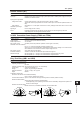
Alarm Output Relay (/A1, /A2, and /A3)
Item Specifications
Action Outputs relay contact signals from the terminals on the rear panel when alarms occur.
Number of outputs 2 outputs (/A1), 4 outputs (/A2), and 6 outputs (/A3)
Relay contact rating 250 VAC (50/60 Hz)/3 A, 250 VDC/0.1 A (for resistance load)
Output format NO-C-NC
Relay operation Energized/deenergized, AND/OR, hold/non-hold, and reflash settings are selectable.
RS-232 Interface (/C2) and RS-422/485 Interface (/C3)
Item Specifications
Connection EIA RS-232(/C2) or EIA RS-422/485(/C3)
Protocol Dedicated protocol or Modbus protocol
Synchronization Start-stop synchronization
Transmission mode (RS-422/485)
Four-wire half-duplex multi-drop connection (1:N (N = 1 to 32))
Data rate 1200, 2400, 4800, 9600, 19200, or 38400 bps
Data length
7 or 8 bits
Stop bit 1 bit
Parity Odd, even, or none
Handshaking Off:Off, XON:XON, XON:RS, and CS:RS
Communication distance (RS-422/485)
1200 m
Modbus communication Operation modes: Master or slave
FAIL/Status Output Relay (/F1)
Item Specifications
Relay operation assignment You can select which operations to assign to the two relays (release numbers 4 and later).
FAIL output Relay contact output on CPU error
Relay operation Energized during normal operation and de-energized on system error.
Status output Output a relay contact signal when a selected condition occurs.
A combination of the following conditions can be selected:
Low memory, memory failure, media error, A/D hardware error, burnout detection, communication
error (Modbus master or client communication error), alarm occurrence
Relay operation Relay is energized when a condition occurs.
Relay contact rating 250 VAC (50/60 Hz)/3
A, 250 VDC/0.1 A (for resistance load)
Clamped Input Terminal (Detachable) (/H2)
Item Specifications
Input terminal Make the input section clamp input terminals (detachable).
Recommended wire size: 0.08 to 1.5 mm
2
(AWG 28 to 16)