
User guide

1-14
IM 04L41B01-01E
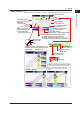
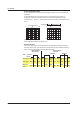
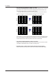
• Partial Expanded Display
By compressing a section of the waveform display range, the rest of the section is
expanded.
In the example below, 0 V (boundary value) is moved to the 30% position of
the display range (new boundary position). The 30% area below the boundary
corresponds to “
–
6 V to 0 V” and 70% area above the boundary corresponds to “0 V
to 6 V.”
100
100
30
0
50
0
6V
6V
0
–6V
–6V
0
Partial Expanded Dispaly
Normal Display
Expanded portion
Compressed portion
% of full display span
Measured valueMeasured value
For the setting procedure, see section 5.9.
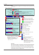
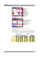
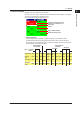
• Alarm Indication
Alarm mark, alarm type, and measured value are displayed as follows according to
the alarm status. When you use the alarm annunciator function (release number 3 or
later), the alarm mark follows the annunciator sequence.
Alarm
Release
Red None Red
None Red RedNone None None None None
Alarm ACK
Alarm ACK
Occurrence
When indication is
set to non-hold
When indication is
set to hold
Alarm type
Red Blue Red
Blue Red RedBlue Blue Blue Blue Blue
Measured
value
Blinking
red
Blinking
green
Blinking
red
Green Red RedGreen Green GreenGreen Green
Alarm mark
1.3 Display