
Manual

3-5
SM 04L41B01-01E
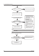
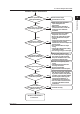
Testing
1
2
3
4
5
6
7
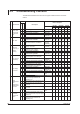
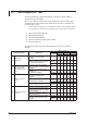
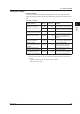
Withstand Voltage
● TestProcedures
Perform the test with a withstanding voltage tester, and check whether the results
satisfy the reference values. Perform the measurement with the power switch turned
ON.
T
est time: 1 minute
Tested Terminals
Applied
Voltage
Maximum Allowable
Leakage Current
Condition
Between the power and
protective ground terminals
2.3 kVAC 10 mA
When /P1 not installed (100–240
VAC). Short the L and N terminals.
0.5 KVAC 10 mA
With /P1 (24 VAC/DC).
Short the L (+) and N (–) terminals.
Between the input and
protective ground terminals
1.5 kVAC 2 mA Short all input terminals.
Between input terminals 1.0 kVAC 1 mA
Short the odd and even channels
of the A/+, B/- terminals*, and
measure between odd and even
channels.
Between relay contact
output and protective
ground terminals
1.6 kVAC 2 mA
With the /A1, /A2, /A3, /A4, /A5
/F1, or /F2 option. Short all relay
contact output terminals.
Between the remote control
input and protective ground
terminals
1.0 kVDC 2 mA
With the /R1 option. Short all
remote control input terminals.
Between pulse input and
protective ground terminals
1.0 kVDC 2 mA
With the /PM1 option. Short all
pulse input terminals.
Between 24 V transmitter
power supply output and
protective ground terminals
500 VAC 10 mA
With the /TPS2, /TPS4, or /TPS8
option. Short all 24 V transmitter
power supply output terminals.
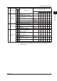
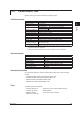
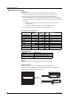
*
The b terminals on the following models are independent on all channels. Short the odd
and even channels of the A/+, B/-, and b terminals, and measure between odd and even
channels.
• DX1002, DX1002N, DX1004, DX1004N, DX2004, DX2008
•
With the /N1 or /N2 option.
3.4 Test Procedures