
Manual

3-2
SM 04L41B01-01E
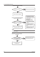
3.2 Self Diagnostic Test
The DX is provided with complete self diagnostic functions to enhance reliability in
measurement and serviceability.
When you turn ON* the power, the DX will automatically execute the following types
of diagnoses alternately and display the results. After these tests are completed, the
recorder is ready for use.
* The DX1000N power supply switch is located inside the bezel. Disconnect then reconnect
the power supply, or open the bezel and operate the power supply switch (see section 7.3).
1.
Main program (Flash ROM) test
2.
Main RAM write/read test
3.
A/D and A/D EEPROM test
4.
Memory acquisition test (write test from Flash)
5.
Ethernet module test
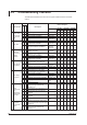
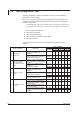
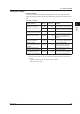
The table below shows the results of the self diagnostic tests when a problem is
detected.
Display upon Error Likely Cause
Refer to Chapter 6
Part Name
DX1000 DX1000N DX2000
Page Item Page Item Page Item
901
902
ROM failure.
RAM failure.
Connection between MAIN BOARD
ASSEMBLY and SUB BOARD
ASSEMBLY
– – – – – –
Replace the SUB BOARD ASSEMBLY
or MAIN BOARD ASSEMBLY
Sub PBA
EXP.BOOT
6-4 13 6-13 15 6-23 19
Main PBA 6-4 12 6-13 14 6-23 18
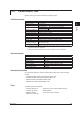
910
921
A/D memory failure for
all input channels.
A/D calibration value
error.
Connection between AD SCANNER
BOARD ASSEMBLY and MAIN BOARD
ASSEMBLY
– – – – – – –
Replace the AD SCANNER BOARD
ASSEMBLY or
MAIN BOARD ASSEMBLY
AD-STD/
ISO
6-4 22 6-13 26 6-23
40, 41,
42, 43
Main PBA 6-4 12 6-13 14 6-23 18
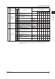
930 Memory acquisition
failure.
Connection between MAIN BOARD
ASSEMBLY and SUB BOARD
ASSEMBLY
– – – – – – –
Replace the SUB BOARD ASSEMBLY
or MAIN BOARD ASSEMBLY
Sub PBA
EXP.BOOT
6-4 13 6-13 15 6-23 19
Main PBA 6-4 12 6-13 14 6-23 18
Replace the internal CF card
CF
Assembly
6-4 26 – – 6-23 47
940 The Ethernet module
is down.
Check communication settings – – – – – – –
Connection between POWER TERM &
COMM BOARD ASSEMBLY and MAIN
BOARD ASSEMBLY
– – – – – – –
Check the communication cables and
LINK LED illumination
– – – – – – –
Replace the MAIN BOARD ASSEMBLY
or POWER TERM & COMM BOARD
ASSEMBLY
Main PBA 6-4 12 6-13 14 6-23 18
S/I-PWR
Terminal
6-6 8,17 6-16 8 6-26
27,38