
Manual

2-4
SM 04L41B01-01E
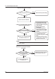
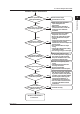
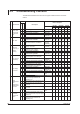
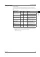
2.2 Troubleshooting Checklist
The table below describes the most common types of failures and their corrective
actions.
No. Phenomenon
Action
Description
Refer to Chapter 6
Check
Adjust
Replace
*1
Part Name
DX1000 DX1000N DX2000
Page Item Page Item Page Item
1
The instrument
doesn’t start
even though
the power is
ON
Power supply cable connection/wiring - - - - - - -
MAIN POWER BOARD ASSEMBLY Power PBA 6-4 4 6-13 3 6-23 6
MAIN BOARD ASSEMBLY Main PBA 6-4 12 6-13 14 6-23 18
SUB BOARD ASSEMBLY
Sub PBA
EXP. BOOT
6-4 13 6-13 15 6-23 19
2 FAIL state
MAIN BOARD ASSEMBLY Main PBA 6-4 12 6-13 14 6-23 18
SUB BOARD ASSEMBLY
Sub PBA
EXP. BOOT
6-4 13 6-13 15 6-23 19
OPTION TERMINAL ASSEMBLY
Option
Terminal
Assembly
6-6 4 6-16 4 6-26
14, 17
20, 23
3
Abnormal
functioning of
memory
(backup)
Battery connection
Battery
Assembly
6-4 14 6-13 16 6-23 20
Battery voltage
(must be +3.0 V or more)
- - - - - - -
MAIN BOARD ASSEMBLY Main PBA 6-4 12 6-13 14 6-23 18
SUB BOARD ASSEMBLY
Sub PBA
EXP. BOOT
6-4 13 6-13 15 6-23 19
4
Key operation
abnormality
Check the FFCs
*2
for key wiring
(whether pulled out or damaged)
- - - - - - -
SW & Sensor BOARD ASSEMBLY
Key Case
Assembly
6-3 14 6-12 20 6-22 4
CONNECTION BOARD ASSEMBLY CONN. PBA 6-3 6 6-12 7 - -
MAIN BOARD ASSEMBLY Main PBA 6-4 12 6-13 14 6-23 18
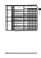
5
LCD display
not normal
Check the FFCs
*2
for key wiring
(whether pulled out or damaged)
- - - - - - -
MAIN BOARD ASSEMBLY Main PBA 6-4 12 6-13 14 6-23 18
SUB BOARD ASSEMBLY
Sub PBA
EXP. BOOT
6-4 13 6-13 15 6-23 19
CONNECTION BOARD ASSEMBLY CONN. PBA 6-3 6 6-12 7 - -
Back Light Unit of LCD ASSEMBLY
Back Light
Unit
6-3 3 6-12 4 6-22 3
LCD & INVERTER UNIT LCD 6-3 3 6-12 4 6-22 1
6
Large
measurement
error
Temperature
measurement
abnormal
Keep input wires away from noise
sources (through distance and
shielding, etc.)
- - - - - - -
Check that the input terminals are not
disconnected from the instrument
- - - - - - -
Check that the input terminal cover is
not loose
- - - - - - -
Check that the RJC (INT/EXT) setting
is correct
- - - - - - -
AD SCANNER BOARD ASSEMBLY
AD-STD/
ISO
6-4 22 6-13 26 6-23
40, 41
42, 43
7
Fluctuation
in measured
values
Does the integral time setting of the
A/D converter match the power supply
frequency?
- - - - - - -
Keep input wires away from noise
sources (through distance and
shielding, etc.)
- - - - - - -