
Instruction Manual

56
IM 04L41B01-02E
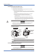
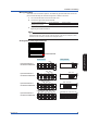
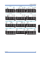
Arrangement of the Optional Terminals
Optional terminal block
02 0104 03
NC
C
NO
NC
C
NO
NC
C
NO
NC
C
NO
NC
C
NO
NC
C
NO
NC
C
NO
NC
C
NO
NC
C
NO
NC
C
NO
NC
C
NO
NC
C
NO
NC
C
NO
NC
C
NO
NC
C
NO
NC
C
NO
NC
C
NO
NC
C
NO
NC
C
NO
NC
C
NO
NC
C
NO
NC
C
NO
NC
C
NO
NC
C
NO
NC
C
NO
NC
C
NO
NC
C
NO
NC
C
NO
NC
C
NO
NC
C
NO
NC
C
NO
NC
C
NO
02 0104 0306 05
C
1
2
8
7
6
5
4
3
C
1
2
8
7
6
5
4
3
C
1
2
8
7
6
5
4
3
C
1
2
8
7
6
5
4
3
C
1
2
8
7
6
5
4
3
NC
NC: Normally closed
C: Common
NO: Normally opened
See page 58.
C
NO
NC
C
NO
NC
02 01
NC
C
NO
NC
C
NO
NC
C
NO
NC
C
NO
C
1
2
8
7
6
5
4
3
NC
C
NO
NC
C
NO
NC
C
NO
NC
C
NO
NC
C
NO
NC
C
NO
NC
C
NO
NC
C
NO
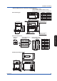
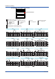
/A1 /A2 /A3
/A1/R1 /A2/R1 /A3/R1
/R1 /A1 /F1 /A2 /F1
/F1 /A1 /F1 /R1 /A2 /F1 /R1
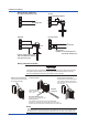
Symbols such as “NC”: Terminal functions
Alarm output, FAIL, Status
1 to 8: Terminal number
C: Common
See page 58.
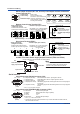
Remote control input
A terminal that is not used. (With a screw)
A terminal that is not used. (Without screw)
Alarm
output
Alarm
output
02 01
Alarm
output
Remote
control
input
02 0104 03
Alarm
output
Remote
control
input
Remote
control
input
02 01
Alarm
output
FAIL
FAIL
02 0102 01
Alarm
output
Remote
control
input
FAIL
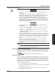
(To next page)
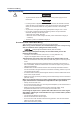
H and L: See page 58.
Pulse input
+ and –: See page 58.
Transmitter power supply
Alarm
output
02 0104 0306 05 02 0104 0306 05
Alarm
output
Remote
control
input
02 0104 03
Alarm
output
FAIL
02 0104 03
Alarm
output
Remote
control
input
FAIL
Status
Status
Status
Status
Status
Installation and Wiring