
Instruction Manual


9
IM 04L41B01-02E
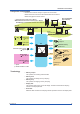
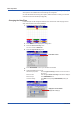
DX System Configuration
The DX can be used to configure a system as shown below.
Referenced sections are of the DX1000/DX1000N User’s Manual.
Referenced pages are of this manual.
Ethernet
Sec. 3.5–3.8
Serial
communication*
RS-232, RS-422/485, or PROFIBUS-DP
*
†
Transmitter power supply
*
Page 58
PC
PLC
PC
DX
RecorderTemperature
controller
FAIL/status output
*
Sec. 2.9
Sec. 2.11
Signal input
Sec. 3.3
Pulse input
*
Sec. 3.10
Sec. 7.1
Sec. 2.10
Page 24
Keys
Sec. 2.11
Sec. 2.12
*: Option
†: Release number 3 or later
PLC (programmable
logic controller)
EtherNet/IP
†
Communication Interface User’s Manual
EtherNet/IP Communication Interface User’s Manual
PROFIBUS-DP Communication Interface User’s Manual
USB port*
Alarm output
*
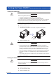
CF card
USB flash memory
Keyboard
Remote Terminal
*
Barcode reader
*
†
Remote input
*
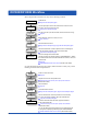
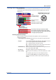
Terminology
• Memory sample
The operation of recording measured data.
• Memory start
The operation of starting memory sampling.
• Memory stop
The operation of stopping memory sampling.
• Display data
The waveform data shown on the DX display. The data recorded at the sampling
interval for the displayed data.
• Event data
Measured data recorded at a sampling interval separate from that of the display data.
Introduction to Functions