
Manual

7
IM 04L41B01-19E
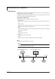
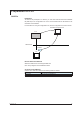
Connection to the PROFIBUS-DP Network
Cable Connection
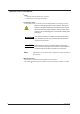
ConnectthePROFIBUS-DPcabletoaPROFIBUS-DPconnectorprovidedontheback
of the DX.
5 4 3 2 1
9 8 7 6
(Rear panel)
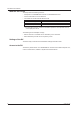
Connector
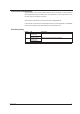
D-sub9-pin(female)connector.Eachpincorrespondstothefollowingsignals.
Pin Signal name Explanation
3 RxD/TxD - P Positivedata
receive/transmit.
4 CNTR - P RTS
(forusebyrepeater).
5 DGND Ground.
6 VP+
5V +5V.
8
RxD/TxD - N Negativedata
receive/transmit.
Pins 1, 2, 7, and 9 are not used.
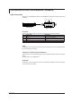
Cable
Adedicatedtwo-wirecableisused(twowiresforthesignal).Thisisnotsuppliedwiththe
DX.Tobepreparedseparately.
Transmission Rate/Transmission Distance
Thetransmissionratevariesdependingonthetransmissiondistancewithinthefollowing
range.
9.6Kbps/1200mto12Mbps/100m
Terminator
TheDXhasnobuilt-interminatorcircuit.Ifaterminatorisneededintermsofwiring,use
a connector with a terminator.