
Manual

12
IM 04L41B01-19E
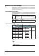
Data Mapping
Datamappingforeachmodelisshowninthetable.Thefollowingsymbolsareusedin
thetable.
Symbol Explanation
CH1, CH2 Data of the measurement channel 1 or measurement channel 2.
CH101, CH112 Data of the computation channel 101 or computation channel 112.
C01, C24
Communication input data.
INT16 16-bitsigned
integer.
INT32_B 32-bitsigned
integer,BigEndian*.
*BigEndian:Assumingthatavalueof01020304Hislocatedas01020304inthebuffer.
Note
• Toacquireaphysicalvalueofthemeasurementchanneldataorcomputationchanneldata,
itisnecessarytoobtainthedecimal place and unitinformationinadvance.
• ThechanneldataorcommunicationinputdatathatcannotbeallocatedintheI/Obufferis
not supported..
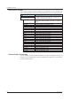
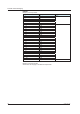
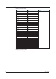
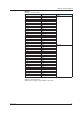
DX1002
Mappingoftheinputbuffer
Offset Description Data type
0 – 1 CH1 INT16
2–
3 CH2
4 – 7 CH
10
1 INT32_B
8–11 CH102
12–15
CH103
16–
19 CH104
20–23
CH105
24 – 27 CH106
28–31 CH107
32–35
CH108
36–
39 CH109
40–43 CH110
44 – 47 CH111
48–51 CH112
52–127 Always0.
-
I/O Buffer and Data Mapping