
Manual

11
IM 04L41B01-19E
I/O Buffer and Data Mapping
Amasterdevicesuchas a PLCaccessesinternaldataof theDXviathe"Input buffer"
and"Outputbuffer"oftheDX."Input"representsaninputtothemaster,while"Output"
represents an output from the master.
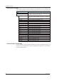
Mapping Method of the I/O buffer
The "Inputbuffer"and"Outputbuffer"oftheDXforPROFIBUS-DPcommunicationhas
128byteseach.Dataislaidoutasdescribedinthefollowingtable.Datalayoutcannot
bechanged.
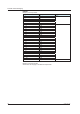
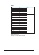
Buffer Application Description
Input Reading
measurement channel
data and computation
channel data
Locates all the measurement channel data from the top of
thebuf
fer.Locatesasmuchcomputationchanneldataas
possibleintheremainingpartofthebuffer.
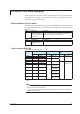
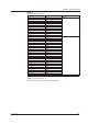
Buffer Application Description
Output Writing
communication input
data
Locates
asmuchcommunicationinputdataaspossible.
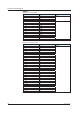
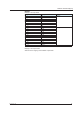
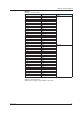
Data Count and Data Type
TheDXdatacountisasfollows:
Model Measurement channel Computation channel Communication input
data
Count Number Count Number Count Number
DX1002
2 001, 002 1
2 101 to 112 24 C01 to C24
DX1004 4 001 to 004
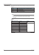
DX1006
6 001to
006 24 101 to 124
DX1012 12 001 to 012
DX2004 4 001 to 004 1
2 101 to 112 60 C01toC32
(C33toC60)
*1
DX2008 8 001to008
DX2010 10 001 to 010 60 101
to 127
(128to160)
*1
DX2020 20 001 to 020 101 to 122
(123to160)
*1
DX2030 30 001to030 101 to 117
(118to160)
*1
DX2040 40 001 to 040 101 to 112
(113to160)
*1
DX2048 48 001to048 101to108
(109to160)
*1
*1DatainparenthesescannotbelocatedinabufferbecauseitexceedsthecapacityoftheI/O
buffer.
Note
The communication input data for C01 to C24 (on the DX1000) or for C01 to C32 (on the
DX2000)isreservedforPROFIBUS-DP.
Youcannotwritetothesedatanumbersthroughothermeans(suchasModbus,EtherNet/IP,or
communication commands).