
Owner manual

2-4
IM 04L41B01-17E
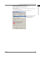
2.3 Connecting the DX
Connecting the cable
Connect a cable to the serial port on the DX rear panel.
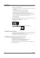
RS-232 Connection Procedure
Connect a cable to the 9-pin D-sub RS-232 connector.
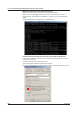
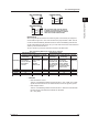
Connector pin arrangement and signal names
2
1 3
4 5
6
7
9
8
(Rear panel)
Each pin corresponds to the signal indicated below.
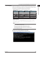
The following table shows the signal name, RS-232 standard, JIS, and ITU-T standard
signals.
Pin Signal Name Name Meaning
JIS ITU-T RS-232
2 RD 104 BB(RXD) Received data Input signal to the DX.
3 SD 103 BA(TXD) Transmitted data Output signal from the DX.
5 SG 102 AB(GND) Signal ground Signal ground.
7 RS 105 CA(RTS) Request to send Handshaking signal when
receiving data from the PC.
Output signal from the DX.
8 CS 106 CB(CTS) Clear to send Handshaking signal when
receiving data from the PC.
Input signal to the DX.
* Pins 1, 4, 6, and 9 are not used.
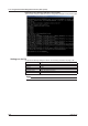
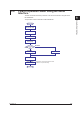
Connection
• Signal direction
PC DX
RS [Request to send...Ready to receive]
SD [Send data]
RD [Received data]
2
3
8
7
CS [Clear to send...Ready]