
Owner manual

6-10
IM 04L41B01-17E
Hold Register (shared with the Modbus slave function)
• Common Items
• The client device can read and write to the hold registers.
• Communication input data is an option (/M1, /PM1).
• External input channels are DX2000 option (/MC1).
When Writing
• Communication input data can be handled on a computation channel by including
the data in the equation of a DX computation channel.
• External input channel data can be handled on an external input channel.
•
Details
• Details
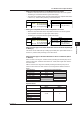
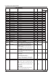
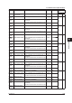
Hold Register Data Data Type
400001 Communication input data C01
16-bit signed integer
| |
400060 Communication input data C60
• Precautions to be taken when the client device reads the data
The communication input data of the DX is floating point type, but the data is converted to
signed 16-bit integer when the data is read.
• Precautions to be taken when the client device writes the data
Only data in signed 16-bit integer type can be written. Floating point values cannot be
written.
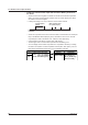
400301 Lower bytes of communication input data C01
32-bit floating point
400302 Higher bytes of communication input data C01
| |
400419 Lower bytes of communication input data C60
400420 Higher bytes of communication input data C60
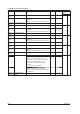
• Precautions to be taken when the client device writes the data
Input range: –9.9999E29 to –1E–30, 0, 1E–30 to 9.9999E29
If values outside this range are used on a computation channel, a computation error
occurs.
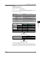
401001 External input channel write register 201
16-bit signed integer
| |
401240 External input channel write register 440
• Precautions to be taken when the client device writes the data
Only data in signed 16-bit integer type can be written.
The measurement range and unit are set using the external input channels. The decimal
point position is determined by the Span_L settings.
6.3 Modbus Protocol Specifications