
Owner manual

6-8
IM 04L41B01-17E
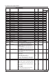
Input Register (shared with the Modbus slave function)
• Common Items
• The client device can only read the input registers.
• Decimal position and unit are not included. Specify them on the client device.
• External input channels are DX2000 option (/MC1).
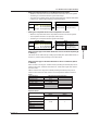
• Details
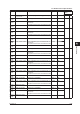
Input Register Data Data Type
300001 Measured data of measurement channel 001
16-bit signed integer
| |
300048 Measured data of measurement channel 048
• There is no decimal position information.
301001 Alarm status of measurement channel 001
Bit string
| |
301048 Alarm status of measurement channel 048
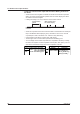
• Register structure and alarm status values
2 1 4 3
4 bits 4 bits 4 bits 4 bits
4-bits
value Meaning
0 No alarm
1 High limit alarm
2 Low limit alarm
3 Difference high limit alarm
4 Difference low limit alarm
5 High limit on rate-of-change alarm
6 Low limit on rate-of-change alarm
7 Delay high limit alarm
8 Delay low limit alarm
Alarm level
Alarm status
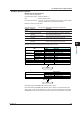
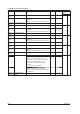
302001 Lower bytes of the computed data of computation channel 101
32-bit signed integer
302002 Higher bytes of the computed data of computation channel 101
| |
302119 Lower bytes of the computed data of computation channel 160
302120 Higher bytes of the computed data of computation channel 160
• Register structure
Example: Channel 101
Higher bytes Lower bytes
Register 302002
Computed data
Register 302001
• There is no decimal position information.
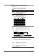
303001 Alarm status of computation channel 101
Bit string
|
303060 Alarm status of computation channel 160
• Register structure and alarm status values: Same as the alarm status of the
measurement channels.
304001 Measured data of external input channel 201
16-bit signed integer
| |
304240 Measured data of external input channel 440
• There is no decimal position information.
305001 Alarm status of external input channel 201
Bit string
| |
305240 Alarm status of external input channel 440
• Register structure and alarm status values: Same as the alarm status of the
measurement channels.
6.3 Modbus Protocol Specifications