
Owner manual


5-2
IM 04L41B01-17E
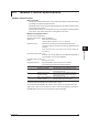
5.2 Bit Structure of the Status Information
The following four groups of status information are output in response to a status
information output request using the IS command. For the output format, see “Status
Information” in section 4.2, “Output Format of ASCII Data.”
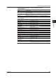
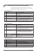
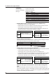
Status Information 1
Bit Name Description
0 Basic setting Set to 1 during basic setting mode.
1 Memory sampling Set to 1 during recording (memory sampling). On models with the multi
batch (/BT2 option), this bit is set to 1 if any batch group is recording
(memory sampling).
2 Computing Set to 1 while computation is in progress.
3 Alarm activated Set to 1 while the alarm is activated.
4 Accessing medium Set to 1 while the display
, event, manual sampled, report, or screen
image data file are being saved to the external storage medium.
5 E-mail started Set to 1 while the e-mail transmission is started
6
Invalid user check operation
*1
Set to 1 only during the period when there is an invalid user and the
invalid user acknowledge operation has not finished (the period during
which the invalid user icon appears on the DX screen).
7 – –
*1 Advanced security (/AS1 option)
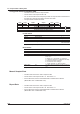
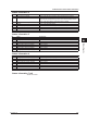
Status Information 2
Bit Name Description
0 Setting function communication login
*1
Set to 1 while a user is logged in to the DX setting function through
Ethernet communication.
1 – –
2 Memory end Set to 1 while the free space in the internal memory or external storage
medium is low. This is the same as the internal memory and CF card
status of the device information output (/F1 or /F2 options; see section 1.9
in the DX1000/DX1000N or DX2000 User's Manual).
3 Logged in through keys Set to 1 while logged in through keys.
4 Login not possible
*1
Set to 1 while the multi-login function is not being used and login
through key operations, login to the setting function through Ethernet
communication, and login through the sending of the LL command
through serial communication are not possible, because another user is
logged in.
5 – –
6 Detecting measurement error Set to 1 while error is being detected in the
A/D converter or a burnout is
being detected.
7 Detecting communication
error Set to 1 if any command is stopping the communication on the Modbus
master or Modbus client.
*1 Advanced security (/AS1 option)
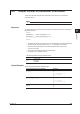
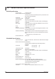
Status Information 3
Bit Name Description
0 Measurement dropout Set to 1 when the measurement process could not keep up.
1 Decimal point/unit information change Set to 1 when the decimal point/unit information is changed.
2 Command error Set to 1 when there is a command syntax error.
3 Execution error Set to 1 when an error occurs during command execution.
4 SNTP error when memory Set to 1 when the time could not be adjusted using SNTP
5 Custom display setup error Set to 1 if an error occurs when a custom display setup file is saved or
loaded.
6 – –
7 – –