
Owner manual

2-13
IM 04L41B01-17E
Using the Serial Interface
1
2
3
4
5
6
App
Index
E-M: Read to the communication input data (32-bit floating point type) from the
server/write the custom display value to the server (release numbers 4 and
later).
R can be selected on DX2000s with the external input channel (/MC1) installed.
R-M, W-M, and E-M can be selected on models with the computation function
(/M1 or /PM1) option installed.
• First/Last (DX’s channel numbers)
Enter the first and last channel numbers of input/output. The range of channels that
you can enter varies depending on the command type as follows:
R: 201 to 440, R-M: C01 to C60, W: 1 to 48, W-M: 101 to 160, E-M: C01 to C60
• Address
Enter the address of the slave device in the range of 1 to 247.
• Regi.
Set the register number of the slave.
For an input register, select in the range of 30001 to 39999 and 300001 to 365536.
For a hold register, select in the range of 40001 to 49999 and 400001 to 465536.
The register numbers you can specify vary depending on the command type. See
section 6.3.
• Type
Select INT16, UINT16, INT32_B, INT32_L, UINT32_B, UINT_L, FLOAT_B, or
FLOAT_L.
The register numbers you can specify vary depending on the command type. See
section 6.3.
Examples of Setting Commands
See page 1-36.
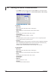
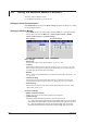
Checking the Modbus Operating Status
Displaying the Modbus Operating Status
◊ Press DISP/ENTER and select INFORMATION > MODBUS MASTER.
Note
To display the MODBUS MASTER on the screen selection menu, you need to change the
setting using the menu cutomize function. Operate as follows:
◊ Press
MENU
(to switch to setting mode), and select the
Menu
tab >
Menu customize
>
Display menu.
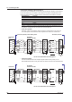
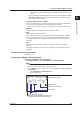
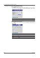
1. Select INFORMATION > MODBUS MASTER
.
2. Press the View soft key.
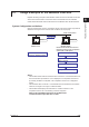
Address for a slave device
Register number
DX channels
Detail code
Status lamp
Cursor to select a command
(Used when resuming command transmission
to a slave device using the front panel keys)
Communication condition
2.6 Using the Modbus Master Function