
Energy Meter Manual


<Toc> <Ind> <5. Modbus/RTU and ASCII Communication Protocols>
5-3
IM 77C01E01-10E
5.1.1 Configuration of Message
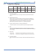
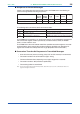
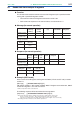
Messages sent from the higher-level device to the PR300 consist of the following elements.
Number of bytes
in RTU mode
None
Number of bytes
in ASCII mode
22
(1) (3) (4) (5)(2) (6)
Element
Station
Number
(ST-NO)
Function
Code
Start of
Message Mark
Data Error Check End of
Message Mark
None
1224n
(variable)
112n
(variable)
2
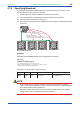
(1) Start of Message Mark
This mark indicates the start of a message. Note that only ASCII mode requires a
colon (:).
(2) Station Number (01 to 99)
Station numbers are used by the higher-level device to identify the PR300 at the
communication destination. (These numbers are identification numbers specific to
individual PR300, which are expressed in hexadecimal in the message.)
00: Broadcasting mode (See subsection 5.1.5, “Specifying Broadcast”)
(3) Function Code (See section 5.2, “Message and Response”)
This element specifies a command (function code) from the higher-level device.
(4) Data
This element specifies D register numbers, the number of D registers, parameter
values, or others in accordance with the function code. (It is expressed in hexadecimal
in the message.)
(5) Error Check
In RTU mode: Carried out by the cyclic redundancy check (CRC-16) system.
In ASCII mode: Carried out by the longitudinal redundancy check (LRC) system.
(6) End of Message Mark
This mark indicates the end of a message. Note that only ASCII mode requires CR +
LF.