
Energy Meter Manual


4-16
<Toc> <Ind> <4. PC Link Communication Protocol>
IM 77C01E01-10E
FA-M3's UT Link Module Setup Procedure (Example)
This section explains the procedure for setting up the FA-M3's UT link module when the
“Automatic mode” is used.
(1) Setting Up the UT Link Module
Before following the procedure, always make sure that the FA-M3's UT link module is
turned off. Then, open the inner cover and follow the setup steps described below.
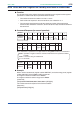
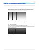
Configure the DIP switch of the UT link module as shown below:
Switch No. Status Description
ON
ON
OFF
Data length: 8 bits
Parity: none (initial value: even)
Stop bit: 1 bit
OFF Checksum: none
ON Termination character: yes (CR)
ON Mode: Automatic mode
OFF Not used.
SW1
SW2, SW3
SW4
SW5
SW6
SW7
SW8
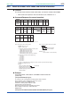
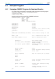
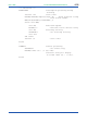
Set the Baud Rate switch to 9600 bps.
Set the Communication Mode switch to 7 (Normal).
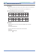
(2) Setting Up the PR300
Set the communication conditions of the PR300 as shown below:
For details on how to set the conditions, see the PR300 Power and Energy Meter Uuser's
Manual (electronic manual).
Parameter Description
PC link communication (without checksum)
8 bits
None
1 bit
9600 bps
Communication protocol
Data length
Parity
Stop bit
Baud rate
(3) Turn on the FA-M3.