
Energy Meter Manual
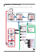
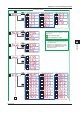
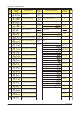
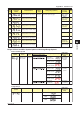
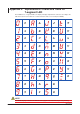
Table Of Contents
- Introduction
- Notices
- Checking the Package
- Checking the Model and Suffix Codes
- Contents
- Chapter 1 Installation and Wiring
- 1.1 Installation with the ANSI 4-inch Round Form or JIS 110-square Instrument Size
- 1.2 Installation with the DIN 96-square Instrument Size
- 1.3 Wiring
- Crimping Terminal Recommendations
- Single-phase two-wire system (voltage input, current input, power supply)
- Single-phase three-wire system (voltage input, current input, power supply)
- Three-phase three-wire system (voltage input, current input, power supply)
- Three-phase four-wire system (voltage input, current input, power supply)
- Three-phase four-wire system (2.5 element) (voltage input, current input, power supply)
- Other Wiring
- 1.4 Attaching the Dust Cover and Terminal Cover
- Chapter 2 Preparations before Starting Measurement (Set up the PR300 First)
- Chapter 3 Parameter Setting Operations
- 3.1 Basic Parameter Setting Operations
- 3.2 Setting the VT and CT Ratios
- 3.3 Setting the Integrated Low-cut Power
- 3.4 Setting RS-485 Communication Conditions
- 3.5 Setting Ethernet Communication Conditions
- 3.6 Setting Pulse Output Conditions
- 3.7 Setting Analog Output Conditions
- 3.8 Setting Demand Measurement Conditions
- 3.9 Setting the Measured Value Display Pattern
- 3.10 Setting the “Indicator-out” Mode and Locking Parameters
- Chapter 4 Operation for Display of Measurement Items and Measurement Method
- 4.1 Measurement Items
- 4.2 Switching Display Pattern
- 4.3 Displaying Measured, Instantaneous, and Maximum/Minimum Values
- Example Display and Measuring Ranges of Active Power (Regenerative Power)
- Example Display and Measuring Ranges of Reactive Power
- Example Display and Measuring Ranges of Apparent Power
- Example Display and Measuring Ranges of Voltage
- Example Display and Measuring Ranges of Current
- Example Display and Measuring Ranges of Power Factor
- Example Display and Measuring Ranges of Frequency
- How to Switch between Instantaneous Value, Maximum Value, and Minimum Value
- 4.4 Phase Switching for Voltage and Current
- 4.5 Displaying Energy Values
- 4.6 Resetting Measured Values
- 4.7 Demand Measurement (Optional Measuring Function)
- Chapter 5 Troubleshooting
- Appendix
- Appendix 1 Specifications of PR300
- Measuring Function
- Power Items and Equations
- Input Specifications
- Digital Input Specifications
- Analog Output Specifications (additional output function)
- Pulse Output Specifications (additional output function)
- Demand Alarm Output Specifications (optional measuring function)
- Communication Specifications
- Standard Performance
- Safety and EMC Standards
- Environmental Conditions
- Mounting and Shape
- Appendix 2 System Reset
- Appendix 3 Parameter Map
- Appendix 4 Parameter List
- Appendix 5 Alphanumeric Characters Table for 7-segment LED
- Appendix 1 Specifications of PR300
- Index
- A
- C
- D
- E
- H
- I
- M
- O
- P
- R
- S
- T
- V
- W
- Wiring diagram
- Single-phase two-wire system
- Single-phase three-wire system
- Three-phase three-wire system
- Three-phase four-wire system
- Three-phase four-wire system (2.5 element)
- Analog output
- Demand alarm output
- Demand alarm release
- Ethernet communication
- Integration control signal
- Palse output
- RS-485 communication
- Wiring diagram

Index-1
IM 77C01E01-01E
1
2
3
4
5
A
I
Index
Index
Index
A
Analog output conditions setting ....................................... 3-12
C
Component names and functions ....................................... 2-1
CT ratio setting .................................................................... 3-3
D
Demand ............................................................................ 4-12
Demand alarm ..............................................................4-14
Demand alarm mask time ............................................. 4-14
Demand alarm release function.................................... 4-14
Demand measurement conditions setting .................... 3-14
Measurement example ................................................. 4-14
Measuring operation ..................................................... 4-13
Measuring range........................................................... 4-12
Display pattern .................................................................... 4-2
Dust cover ........................................................................... 1-9
E
Energy value display operation ........................................... 4-8
Error display and recommended response ......................... 5-1
Ethernet communication conditions setting ........................ 3-8
External Dimensions
ANSI 4-inch round form size........................................... 1-1
DIN 96-square instrument size ....................................... 1-3
H
How to switch between instantaneous value, maximum ..... 4-5
I
Indicator-out mode setting ................................................ 3-19
Integrated low-cut power ..................................................... 3-5
Integrated low-cut power setting ......................................... 3-4
M
Measured value display pattern setting ............................ 3-16
Measured value reset ....................................................... 4-10
Measurement items ............................................................ 4-1
Measuring range
Active energy .................................................................. 4-7
Active power ................................................................... 4-3
Apparent energy ............................................................. 4-7
Apparent power .............................................................. 4-3
Current............................................................................ 4-4
Frequency....................................................................... 4-5
Power factor ................................................................... 4-4
Reactive energy.............................................................. 4-7
Reactive power ............................................................... 4-3
Regenerative energy ...................................................... 4-7
Regenerative power ....................................................... 4-3
Voltage............................................................................ 4-4
Mounting method
ANSI 4-inch round form size........................................... 1-2
DIN 96-square instrument size ....................................... 1-4
O
Optional integrating function ............................................... 4-9
P
Panel cutout dimensions
ANSI ............................................................................... 1-1
DIN ................................................................................. 1-3
Parameter list ................................................................... A-12
Parameter lock and Unlock ............................................... 3-20
Parameter map ................................................................ A-10
Parameter setting
Analog output conditions .............................................. 3-12
CT ratio ........................................................................... 3-3
Demand measurement conditions ................................ 3-14
Ethernet communication conditions ................................ 3-8
Indicator-out mode........................................................ 3-19
Integrated low-cut power ................................................ 3-4
Measured value display pattern.................................... 3-16
Phase and wire system .................................................. 2-2
Pulse output conditions ................................................ 3-10
RS-485 Communication Conditions ............................... 3-6
Voltage range ................................................................. 2-4
VT ratio ........................................................................... 3-2
Phase and wire system setting ........................................... 2-2
Phase switching .................................................................. 4-6
Pulse output conditions setting ......................................... 3-10
R
RS-485 communication conditions setting .......................... 3-6
S
Specifications
Analog output specifications .......................................... A-3
Communication specifications ....................................... A-4
Compliance with safety and EMC standards ................. A-7
Demand alarm Output specifications............................. A-4
Digital input specifications ............................................. A-3
Environmental Conditions.............................................. A-8
Input specifications ........................................................ A-2
Measuring function ........................................................ A-1
Mounting and Shape ..................................................... A-8
Pulse output specifications ............................................ A-3
Standard performance ................................................... A-6
System reset ...................................................................... A-9
T
Terminal cover ..................................................................... 1-9
V
Voltage range setting .......................................................... 2-4
VT ratio setting .................................................................... 3-2