
Energy Meter Manual
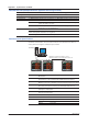


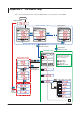
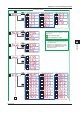
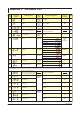
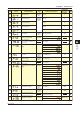
Table Of Contents
- Introduction
- Notices
- Checking the Package
- Checking the Model and Suffix Codes
- Contents
- Chapter 1 Installation and Wiring
- 1.1 Installation with the ANSI 4-inch Round Form or JIS 110-square Instrument Size
- 1.2 Installation with the DIN 96-square Instrument Size
- 1.3 Wiring
- Crimping Terminal Recommendations
- Single-phase two-wire system (voltage input, current input, power supply)
- Single-phase three-wire system (voltage input, current input, power supply)
- Three-phase three-wire system (voltage input, current input, power supply)
- Three-phase four-wire system (voltage input, current input, power supply)
- Three-phase four-wire system (2.5 element) (voltage input, current input, power supply)
- Other Wiring
- 1.4 Attaching the Dust Cover and Terminal Cover
- Chapter 2 Preparations before Starting Measurement (Set up the PR300 First)
- Chapter 3 Parameter Setting Operations
- 3.1 Basic Parameter Setting Operations
- 3.2 Setting the VT and CT Ratios
- 3.3 Setting the Integrated Low-cut Power
- 3.4 Setting RS-485 Communication Conditions
- 3.5 Setting Ethernet Communication Conditions
- 3.6 Setting Pulse Output Conditions
- 3.7 Setting Analog Output Conditions
- 3.8 Setting Demand Measurement Conditions
- 3.9 Setting the Measured Value Display Pattern
- 3.10 Setting the “Indicator-out” Mode and Locking Parameters
- Chapter 4 Operation for Display of Measurement Items and Measurement Method
- 4.1 Measurement Items
- 4.2 Switching Display Pattern
- 4.3 Displaying Measured, Instantaneous, and Maximum/Minimum Values
- Example Display and Measuring Ranges of Active Power (Regenerative Power)
- Example Display and Measuring Ranges of Reactive Power
- Example Display and Measuring Ranges of Apparent Power
- Example Display and Measuring Ranges of Voltage
- Example Display and Measuring Ranges of Current
- Example Display and Measuring Ranges of Power Factor
- Example Display and Measuring Ranges of Frequency
- How to Switch between Instantaneous Value, Maximum Value, and Minimum Value
- 4.4 Phase Switching for Voltage and Current
- 4.5 Displaying Energy Values
- 4.6 Resetting Measured Values
- 4.7 Demand Measurement (Optional Measuring Function)
- Chapter 5 Troubleshooting
- Appendix
- Appendix 1 Specifications of PR300
- Measuring Function
- Power Items and Equations
- Input Specifications
- Digital Input Specifications
- Analog Output Specifications (additional output function)
- Pulse Output Specifications (additional output function)
- Demand Alarm Output Specifications (optional measuring function)
- Communication Specifications
- Standard Performance
- Safety and EMC Standards
- Environmental Conditions
- Mounting and Shape
- Appendix 2 System Reset
- Appendix 3 Parameter Map
- Appendix 4 Parameter List
- Appendix 5 Alphanumeric Characters Table for 7-segment LED
- Appendix 1 Specifications of PR300
- Index
- A
- C
- D
- E
- H
- I
- M
- O
- P
- R
- S
- T
- V
- W
- Wiring diagram
- Single-phase two-wire system
- Single-phase three-wire system
- Three-phase three-wire system
- Three-phase four-wire system
- Three-phase four-wire system (2.5 element)
- Analog output
- Demand alarm output
- Demand alarm release
- Ethernet communication
- Integration control signal
- Palse output
- RS-485 communication
- Wiring diagram

Appendix
A-7
IM 77C01E01-01E
1
2
3
4
5
A
Appendix 1 Specifications of PR300
Insulation resistance Between each of the voltage input, current input, power, ground, digital input, pulse output,
analog output, RS-485 communication output, Ethernet communication output, and alarm
output terminals: 100 M minimum (at 500 V DC)
Withstand voltage Between each of the voltage input, current input, power, and ground terminals: 2500 V AC for 1
minute
Between (the voltage input, current input, power, and ground terminals) and the digital input,
pulse output, analog output, alarm output, RS-485 communication output, and Ethernet
communication output terminals: 2500 V AC for 1 minute
Between each of the digital intput, pulse output, analog output, alarm output, and (RS-485
communication output, Ethernet communication output) terminals: 1000 V AC for 1 minute
Between the RS-485 communication output and Ethernet communication output terminals: 500 V
AC for 1 minute
Impulse withstand voltage
Between all of the voltage input, current input, and power terminals and the ground terminal
Between all of the output and ground terminals and all of the voltage and current input terminals:
6 kV (1.2/50 µs), 10 times for positive and negative
Effects of magnetic field
400 A/m or less Active power: ±0.5% of F.S., Voltage: ±0.25% of F.S.
Effects of changes in ambient temperature
±0.03%/°C for a temperature change rate of 10°C/h or less (when 0.05In I Imax and power factor = 1)
±0.05%/°C for a temperature change rate of 10°C/h or less (when 0.1In I Imax and power factor = LAG0.5)
In: rated current; I: present current input
Effects of power supply voltage variations
Active power: ±0.25%, Voltage/Current: ±0.125%
(for variations within the power supply operating range (when 0.01In and power factor = 1))
In: rated current
Effects of input frequency
Active power: ±0.25%, Voltage/Current: ±0.125% (for variations of 45 to 65 Hz)
Power supply 100 - 240 V AC 10% (50/60 Hz) or 130 - 300 V DC 15%
Power consumption AC drive 10 VA maximum
DC drive 5 W maximum
Safety and EMC Standards
Safety standards Compliant with
IEC/EN61010-1
UL61010-1
CAN/CSA C22.2 No.61010-1-04 (C-UL Listed)
Measurement category: 600V CAT.III
Measurement
category
CAT.I
CAT.II
CAT.III
CAT.IV
Descriptions
Circuits not directly connected to the main power
supply
Circuits directly connected to low-voltage facility
Circuits in building facility
Power sources for low-voltage facility
Remarks
House-use equipment, portable
tools, etc.
Switchboards, circuit breakers, etc.
Overhead lines, cable systems, etc.
Mains supply installation category: CAT.II
Pollution degree: 2 (IEC/EN61010-1)
Rated measurement input
Voltage input: 600 V AC (between terminals)
Current input: 600 V AC (across ground)
EMC-compliant standard
Compliant with EN61326
During testing, the instrument continues to operate at a measurement accuracy within 20%.