
Energy Meter Manual
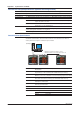
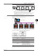


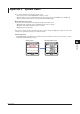
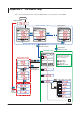
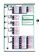
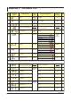
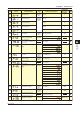
Table Of Contents
- Introduction
- Notices
- Checking the Package
- Checking the Model and Suffix Codes
- Contents
- Chapter 1 Installation and Wiring
- 1.1 Installation with the ANSI 4-inch Round Form or JIS 110-square Instrument Size
- 1.2 Installation with the DIN 96-square Instrument Size
- 1.3 Wiring
- Crimping Terminal Recommendations
- Single-phase two-wire system (voltage input, current input, power supply)
- Single-phase three-wire system (voltage input, current input, power supply)
- Three-phase three-wire system (voltage input, current input, power supply)
- Three-phase four-wire system (voltage input, current input, power supply)
- Three-phase four-wire system (2.5 element) (voltage input, current input, power supply)
- Other Wiring
- 1.4 Attaching the Dust Cover and Terminal Cover
- Chapter 2 Preparations before Starting Measurement (Set up the PR300 First)
- Chapter 3 Parameter Setting Operations
- 3.1 Basic Parameter Setting Operations
- 3.2 Setting the VT and CT Ratios
- 3.3 Setting the Integrated Low-cut Power
- 3.4 Setting RS-485 Communication Conditions
- 3.5 Setting Ethernet Communication Conditions
- 3.6 Setting Pulse Output Conditions
- 3.7 Setting Analog Output Conditions
- 3.8 Setting Demand Measurement Conditions
- 3.9 Setting the Measured Value Display Pattern
- 3.10 Setting the “Indicator-out” Mode and Locking Parameters
- Chapter 4 Operation for Display of Measurement Items and Measurement Method
- 4.1 Measurement Items
- 4.2 Switching Display Pattern
- 4.3 Displaying Measured, Instantaneous, and Maximum/Minimum Values
- Example Display and Measuring Ranges of Active Power (Regenerative Power)
- Example Display and Measuring Ranges of Reactive Power
- Example Display and Measuring Ranges of Apparent Power
- Example Display and Measuring Ranges of Voltage
- Example Display and Measuring Ranges of Current
- Example Display and Measuring Ranges of Power Factor
- Example Display and Measuring Ranges of Frequency
- How to Switch between Instantaneous Value, Maximum Value, and Minimum Value
- 4.4 Phase Switching for Voltage and Current
- 4.5 Displaying Energy Values
- 4.6 Resetting Measured Values
- 4.7 Demand Measurement (Optional Measuring Function)
- Chapter 5 Troubleshooting
- Appendix
- Appendix 1 Specifications of PR300
- Measuring Function
- Power Items and Equations
- Input Specifications
- Digital Input Specifications
- Analog Output Specifications (additional output function)
- Pulse Output Specifications (additional output function)
- Demand Alarm Output Specifications (optional measuring function)
- Communication Specifications
- Standard Performance
- Safety and EMC Standards
- Environmental Conditions
- Mounting and Shape
- Appendix 2 System Reset
- Appendix 3 Parameter Map
- Appendix 4 Parameter List
- Appendix 5 Alphanumeric Characters Table for 7-segment LED
- Appendix 1 Specifications of PR300
- Index
- A
- C
- D
- E
- H
- I
- M
- O
- P
- R
- S
- T
- V
- W
- Wiring diagram
- Single-phase two-wire system
- Single-phase three-wire system
- Three-phase three-wire system
- Three-phase four-wire system
- Three-phase four-wire system (2.5 element)
- Analog output
- Demand alarm output
- Demand alarm release
- Ethernet communication
- Integration control signal
- Palse output
- RS-485 communication
- Wiring diagram
A-6
IM 77C01E01-01E
Appendix 1 Specifications of PR300
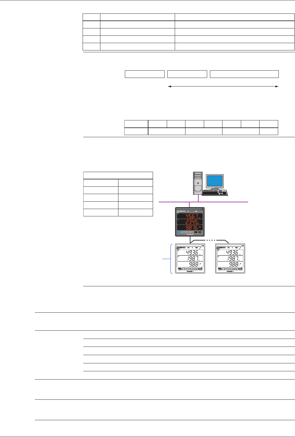
Modbus/TCP function
Code
03
06
08
16
Function
Reads data from multiple D registers
Writes data into D register
Performs loopback test
Writes data into multiple D registers
Description
Capable of reading data from up to 64 registers continuously.
Capable of writing data into one resiter.
Capable of performing a communication test.
Capable of writing data into up to 32 registers continuously.
Overview of Modbus/TCP protocol
PDU
The Simple Protocol Data Unit (PDU) is the same as
Modbus/RTU (Modbus protocol via serial communication).
MBAP Header Function code Data
The structure of the Modbus/TCP protocol is as follows:
Byte No
Description
0
Transaction ID
12
Protocol ID
34
Number of bytes
56
Unit ID
The Modbus Application Protocol Header (MBAP Header) is made of the
following seven bytes:
Ethernet - Serial gateway function
Equipped with an Ethernet communication connector and an RS-485 communication terminal, the
PR300 receives a Modbus/TCP command from Ethernet and relays it to the RS-485 communication
terminal. The PR300 allows connection to RS-485 serial communication devices (Modbus/RTU
protocol) via the network.
Higher-level device
IP address [192.168.1.1]
(arbitrary)
Ethernet
10BASE-T/100BASE-TX
Station number 01 (fixed)
IP address [192.168.1.2] (arbitrary)
PR300 (with Ethernet
communication function)
RS-485 connection
Station number 02
(arbitrary)
Station number 10
(arbitrary)
RS-485 serial communication device
Power monitor of POWERCERT Series
Digital indicating controller of GREEN Series
Signal conditioner of JUXTA Series
(Example)
RS-485 communication
Protocol
Baud rate
Parity
Stop bit
Data length
Modbus/RTU
9600bps
None, even, odd
1 bit
8 bits
(Note) If Ethernet communication is used, the RS-485 communication interface is
used specifically for the Ethernet-serial gateway function. Therefore, it is not
possible for a higher-level device such as a PC to access the PR300 via the
RS-485 communication interface.
Standard Performance
Accuracy rating
Active energy/optional active energy (Wh)
0.5% (EN60687 accuracy: Class 0.5 or equivalent)
Active power (W) 0.5% of F.S.
Voltage (V) 0.25% of F.S. (voltage rms)
Current (A) 0.25% of F.S. (current rms)
Frequency (Hz) 0.5Hz
Demand 0.5%
Calculation accuracy The value is calculated to 1 digit from the measured value for reactive energy, apparent
energy, reactive power, apparent power, power factor, or current.*
* Current is only for the 2.5-element measurement.
Backup upon power failure
The last integrated values obtained immediately before the power failure are held for active
energy, regenerative energy, reactive energy, and apparent energy.