
Energy Meter Manual
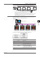
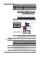

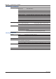
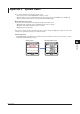
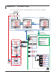
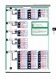
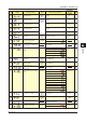
Table Of Contents
- Introduction
- Notices
- Checking the Package
- Checking the Model and Suffix Codes
- Contents
- Chapter 1 Installation and Wiring
- 1.1 Installation with the ANSI 4-inch Round Form or JIS 110-square Instrument Size
- 1.2 Installation with the DIN 96-square Instrument Size
- 1.3 Wiring
- Crimping Terminal Recommendations
- Single-phase two-wire system (voltage input, current input, power supply)
- Single-phase three-wire system (voltage input, current input, power supply)
- Three-phase three-wire system (voltage input, current input, power supply)
- Three-phase four-wire system (voltage input, current input, power supply)
- Three-phase four-wire system (2.5 element) (voltage input, current input, power supply)
- Other Wiring
- 1.4 Attaching the Dust Cover and Terminal Cover
- Chapter 2 Preparations before Starting Measurement (Set up the PR300 First)
- Chapter 3 Parameter Setting Operations
- 3.1 Basic Parameter Setting Operations
- 3.2 Setting the VT and CT Ratios
- 3.3 Setting the Integrated Low-cut Power
- 3.4 Setting RS-485 Communication Conditions
- 3.5 Setting Ethernet Communication Conditions
- 3.6 Setting Pulse Output Conditions
- 3.7 Setting Analog Output Conditions
- 3.8 Setting Demand Measurement Conditions
- 3.9 Setting the Measured Value Display Pattern
- 3.10 Setting the “Indicator-out” Mode and Locking Parameters
- Chapter 4 Operation for Display of Measurement Items and Measurement Method
- 4.1 Measurement Items
- 4.2 Switching Display Pattern
- 4.3 Displaying Measured, Instantaneous, and Maximum/Minimum Values
- Example Display and Measuring Ranges of Active Power (Regenerative Power)
- Example Display and Measuring Ranges of Reactive Power
- Example Display and Measuring Ranges of Apparent Power
- Example Display and Measuring Ranges of Voltage
- Example Display and Measuring Ranges of Current
- Example Display and Measuring Ranges of Power Factor
- Example Display and Measuring Ranges of Frequency
- How to Switch between Instantaneous Value, Maximum Value, and Minimum Value
- 4.4 Phase Switching for Voltage and Current
- 4.5 Displaying Energy Values
- 4.6 Resetting Measured Values
- 4.7 Demand Measurement (Optional Measuring Function)
- Chapter 5 Troubleshooting
- Appendix
- Appendix 1 Specifications of PR300
- Measuring Function
- Power Items and Equations
- Input Specifications
- Digital Input Specifications
- Analog Output Specifications (additional output function)
- Pulse Output Specifications (additional output function)
- Demand Alarm Output Specifications (optional measuring function)
- Communication Specifications
- Standard Performance
- Safety and EMC Standards
- Environmental Conditions
- Mounting and Shape
- Appendix 2 System Reset
- Appendix 3 Parameter Map
- Appendix 4 Parameter List
- Appendix 5 Alphanumeric Characters Table for 7-segment LED
- Appendix 1 Specifications of PR300
- Index
- A
- C
- D
- E
- H
- I
- M
- O
- P
- R
- S
- T
- V
- W
- Wiring diagram
- Single-phase two-wire system
- Single-phase three-wire system
- Three-phase three-wire system
- Three-phase four-wire system
- Three-phase four-wire system (2.5 element)
- Analog output
- Demand alarm output
- Demand alarm release
- Ethernet communication
- Integration control signal
- Palse output
- RS-485 communication
- Wiring diagram
Appendix
A-5
IM 77C01E01-01E
1
2
3
4
5
A
Appendix 1 Specifications of PR300
Example of connection diagram
(SG)
(SG)(SG)
(Bⴙ)(Aⴚ)(Bⴙ)(Aⴚ)
(FG)
Terminator
RS-485RS-485RS-485
Maximum distance: about 1.2 km (31 units maximum)
PC
RS-232C/RS-485
converter
RS-232C
straight
cable
120 external
PR300 PR300 PR300
<Note>
For RS-485 communication, the PR300 employs the two-wire system.
SG: Connection to Terminal SG is made to adjust the signal level of the RS-485 communication line.
FG: For noise protection, a shield line must be connected to all wires in the RS-485 communication line and grounded
at one location.
Use UL Listed RS-232C/RS-485 converter if the converter has AC/DC power supply input; this is optional for
converters supplied by a Limited Power Source with input voltages less than 30 V AC or 60 V DC and which are
separated from mains by double or reinforced insulation.
120 (built-in)
(Aⴚ)
(TERM)
(SG)
(Bⴙ)
(Aⴚ)
(Bⴙ)
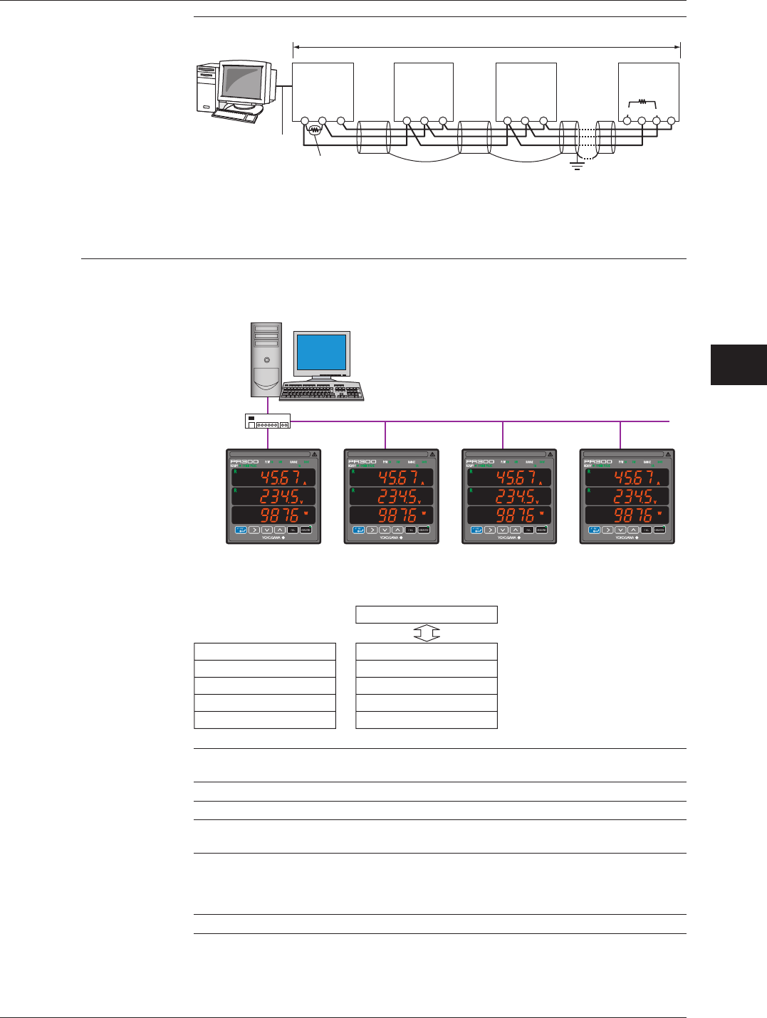
Ethernet communication
Via Ethernet communication, various measured values are read, and values are written to
various parameters using the command/response method.
PC
IP address [192.168.1.1]
Ethernet
LAN connection
HUB
Station number 01
IP address [192.168.1.2]
Station number 01
IP address [192.168.1.3]
Station number 01
IP address [192.168.1.4]
Station number 01
IP address [192.168.1.5]
(Example)
Connectable to an IEEE802.3-compliant network (10BASE-T/100BASE-TX).
Application layer
Transport layer
Network layer
Data link layer
Physical layer
MODBUS/TCP
TCP, UDP
IP, ICMP, ARP
Ethernet
10BASE-T/100BASE-TX
Higher-level device (PC etc.)
Communication specifications
Protocol Modbus/TCP
Access control CSMA/CD
Baud rate 10Mbps/100Mbps
Maximum segment length
100m (between HUB and module)
Maximum connection configuration
Cascade 4 segments maximum (10BASE-T)
2 segments maximum (100BASE-TX)
(number of HUBs that can be cascade connected)
IP address The IP address can be set using the operation keys on the front side of the PR300.