
Energy Meter Manual
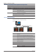
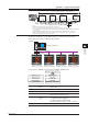
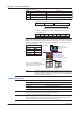

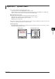
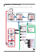
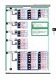
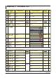
Table Of Contents
- Introduction
- Notices
- Checking the Package
- Checking the Model and Suffix Codes
- Contents
- Chapter 1 Installation and Wiring
- 1.1 Installation with the ANSI 4-inch Round Form or JIS 110-square Instrument Size
- 1.2 Installation with the DIN 96-square Instrument Size
- 1.3 Wiring
- Crimping Terminal Recommendations
- Single-phase two-wire system (voltage input, current input, power supply)
- Single-phase three-wire system (voltage input, current input, power supply)
- Three-phase three-wire system (voltage input, current input, power supply)
- Three-phase four-wire system (voltage input, current input, power supply)
- Three-phase four-wire system (2.5 element) (voltage input, current input, power supply)
- Other Wiring
- 1.4 Attaching the Dust Cover and Terminal Cover
- Chapter 2 Preparations before Starting Measurement (Set up the PR300 First)
- Chapter 3 Parameter Setting Operations
- 3.1 Basic Parameter Setting Operations
- 3.2 Setting the VT and CT Ratios
- 3.3 Setting the Integrated Low-cut Power
- 3.4 Setting RS-485 Communication Conditions
- 3.5 Setting Ethernet Communication Conditions
- 3.6 Setting Pulse Output Conditions
- 3.7 Setting Analog Output Conditions
- 3.8 Setting Demand Measurement Conditions
- 3.9 Setting the Measured Value Display Pattern
- 3.10 Setting the “Indicator-out” Mode and Locking Parameters
- Chapter 4 Operation for Display of Measurement Items and Measurement Method
- 4.1 Measurement Items
- 4.2 Switching Display Pattern
- 4.3 Displaying Measured, Instantaneous, and Maximum/Minimum Values
- Example Display and Measuring Ranges of Active Power (Regenerative Power)
- Example Display and Measuring Ranges of Reactive Power
- Example Display and Measuring Ranges of Apparent Power
- Example Display and Measuring Ranges of Voltage
- Example Display and Measuring Ranges of Current
- Example Display and Measuring Ranges of Power Factor
- Example Display and Measuring Ranges of Frequency
- How to Switch between Instantaneous Value, Maximum Value, and Minimum Value
- 4.4 Phase Switching for Voltage and Current
- 4.5 Displaying Energy Values
- 4.6 Resetting Measured Values
- 4.7 Demand Measurement (Optional Measuring Function)
- Chapter 5 Troubleshooting
- Appendix
- Appendix 1 Specifications of PR300
- Measuring Function
- Power Items and Equations
- Input Specifications
- Digital Input Specifications
- Analog Output Specifications (additional output function)
- Pulse Output Specifications (additional output function)
- Demand Alarm Output Specifications (optional measuring function)
- Communication Specifications
- Standard Performance
- Safety and EMC Standards
- Environmental Conditions
- Mounting and Shape
- Appendix 2 System Reset
- Appendix 3 Parameter Map
- Appendix 4 Parameter List
- Appendix 5 Alphanumeric Characters Table for 7-segment LED
- Appendix 1 Specifications of PR300
- Index
- A
- C
- D
- E
- H
- I
- M
- O
- P
- R
- S
- T
- V
- W
- Wiring diagram
- Single-phase two-wire system
- Single-phase three-wire system
- Three-phase three-wire system
- Three-phase four-wire system
- Three-phase four-wire system (2.5 element)
- Analog output
- Demand alarm output
- Demand alarm release
- Ethernet communication
- Integration control signal
- Palse output
- RS-485 communication
- Wiring diagram
A-4
IM 77C01E01-01E
Appendix 1 Specifications of PR300
Demand Alarm Output Specifications (optional measuring function)
When the demand measurement value exceeds the set demand alarm point, an alarm is triggered.
Output signal Open collector
Contact capacity 30 V DC, 200 mA
Set alarm range 1 to 1000 kW (during demand power measurement); 1 to 1000 A (during demand current measurement)
Alarm release function
Automatic release:When the measured value falls below the demand alarm point during alarm
output, the alarm is canceled.
Manual release: Used to keep the alarm turned on or to cancel it by digital input or the
operation key, or via communication.
* The demand alarm mask time can be set for the PR300.
The demand alarm mask time is the time between the beginning of the demand period and the
set time, during which an alarm is not recognized.
Allowable range of set time: 1 minute to demand period
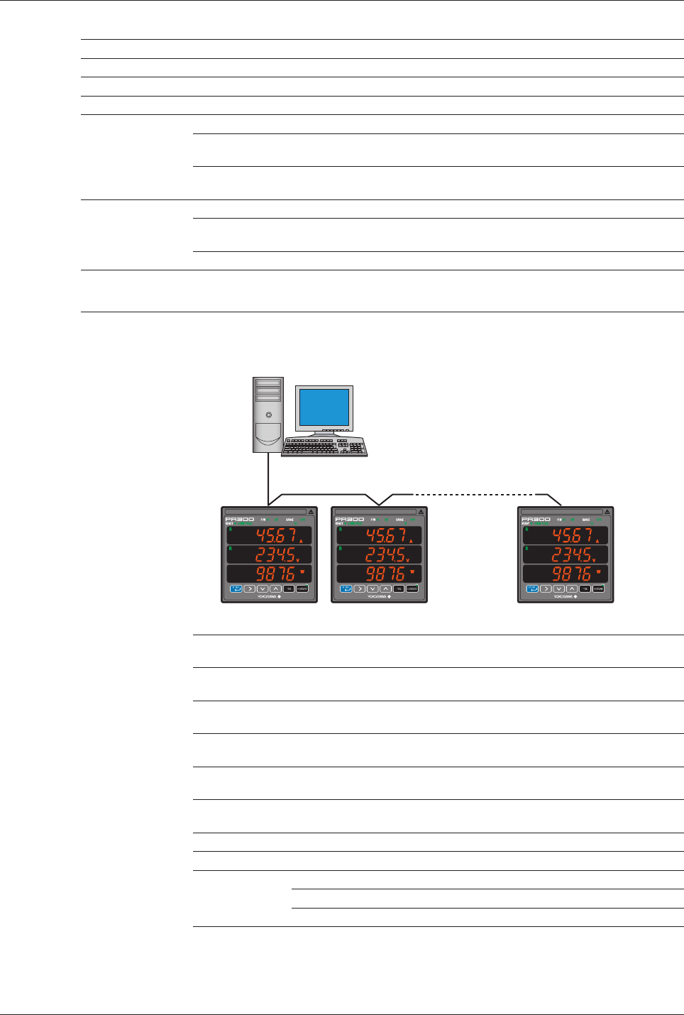
Communication Specifications
RS-485 communication
Via RS-485 communication, various measured values are read, and values are written to
various parameters using the command/response method.
Maximum communication distance: 1.2 km
Maximum number of connectable slave stations: 31
PC
Station number 01 Station number 02 Station number 31
(Example)
Protocol PC link (without checksum), PC link (with checksum), Modbus/ASCII, and
Modbus/RTU
Transmission distance
Approximately 1.2 km maximum (with 24AWG twisted-pair cable(s))
Connection method
Multi-drop connection (a maximum of 32 units including a higher-level device)
Station number 01 to 99 (maximum number of units to be connected: 31 [number of units
that can be connected to a PC etc.]) (recommended value: 01 to 31)
Transmission method
Half-duplex communication
Synchronization
Start-stop synchronization
Baud rate 19200/9600/2400 bps
Xon/Xoff control None
Data format Data length 8 bits, 7 bits
Parity None, even, odd
Stop bit 1 bit, 2 bits