
Energy Meter Manual
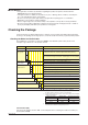
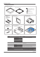
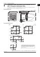

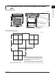
Table Of Contents
- Introduction
- Notices
- Checking the Package
- Checking the Model and Suffix Codes
- Contents
- Chapter 1 Installation and Wiring
- 1.1 Installation with the ANSI 4-inch Round Form or JIS 110-square Instrument Size
- 1.2 Installation with the DIN 96-square Instrument Size
- 1.3 Wiring
- Crimping Terminal Recommendations
- Single-phase two-wire system (voltage input, current input, power supply)
- Single-phase three-wire system (voltage input, current input, power supply)
- Three-phase three-wire system (voltage input, current input, power supply)
- Three-phase four-wire system (voltage input, current input, power supply)
- Three-phase four-wire system (2.5 element) (voltage input, current input, power supply)
- Other Wiring
- 1.4 Attaching the Dust Cover and Terminal Cover
- Chapter 2 Preparations before Starting Measurement (Set up the PR300 First)
- Chapter 3 Parameter Setting Operations
- 3.1 Basic Parameter Setting Operations
- 3.2 Setting the VT and CT Ratios
- 3.3 Setting the Integrated Low-cut Power
- 3.4 Setting RS-485 Communication Conditions
- 3.5 Setting Ethernet Communication Conditions
- 3.6 Setting Pulse Output Conditions
- 3.7 Setting Analog Output Conditions
- 3.8 Setting Demand Measurement Conditions
- 3.9 Setting the Measured Value Display Pattern
- 3.10 Setting the “Indicator-out” Mode and Locking Parameters
- Chapter 4 Operation for Display of Measurement Items and Measurement Method
- 4.1 Measurement Items
- 4.2 Switching Display Pattern
- 4.3 Displaying Measured, Instantaneous, and Maximum/Minimum Values
- Example Display and Measuring Ranges of Active Power (Regenerative Power)
- Example Display and Measuring Ranges of Reactive Power
- Example Display and Measuring Ranges of Apparent Power
- Example Display and Measuring Ranges of Voltage
- Example Display and Measuring Ranges of Current
- Example Display and Measuring Ranges of Power Factor
- Example Display and Measuring Ranges of Frequency
- How to Switch between Instantaneous Value, Maximum Value, and Minimum Value
- 4.4 Phase Switching for Voltage and Current
- 4.5 Displaying Energy Values
- 4.6 Resetting Measured Values
- 4.7 Demand Measurement (Optional Measuring Function)
- Chapter 5 Troubleshooting
- Appendix
- Appendix 1 Specifications of PR300
- Measuring Function
- Power Items and Equations
- Input Specifications
- Digital Input Specifications
- Analog Output Specifications (additional output function)
- Pulse Output Specifications (additional output function)
- Demand Alarm Output Specifications (optional measuring function)
- Communication Specifications
- Standard Performance
- Safety and EMC Standards
- Environmental Conditions
- Mounting and Shape
- Appendix 2 System Reset
- Appendix 3 Parameter Map
- Appendix 4 Parameter List
- Appendix 5 Alphanumeric Characters Table for 7-segment LED
- Appendix 1 Specifications of PR300
- Index
- A
- C
- D
- E
- H
- I
- M
- O
- P
- R
- S
- T
- V
- W
- Wiring diagram
- Single-phase two-wire system
- Single-phase three-wire system
- Three-phase three-wire system
- Three-phase four-wire system
- Three-phase four-wire system (2.5 element)
- Analog output
- Demand alarm output
- Demand alarm release
- Ethernet communication
- Integration control signal
- Palse output
- RS-485 communication
- Wiring diagram

TOC-1
IM 77C01E01-01E
1
1
2
3
4
5
A
I
Model PR300 Power and Energy Meter
IM 77C01E01-01E
Contents
Introduction....................................................................................................................i
Notices ..................................................................................................................... ii
Checking the Package ................................................................................................ iii
■ Checking the Model and Suffix Codes ...................................................................................... iii
■ Checking the Accessories ......................................................................................................... iv
Chapter 1 Installation and Wiring
1.1 Installation with the ANSI 4-inch Round Form or JIS 110-square Instrument Size............ 1-1
External Dimensions ...................................................................................................................1-1
Panel Cutout Dimensions ...........................................................................................................1-1
Mounting Method.........................................................................................................................1-2
1.2 Installation with the DIN 96-square Instrument Size .......................................................... 1-3
External Dimensions ...................................................................................................................1-3
Panel Cutout Dimensions ...........................................................................................................1-3
Mounting Method.........................................................................................................................1-4
1.3 Wiring ..................................................................................................................................1-5
Crimping Terminal Recommendations ........................................................................................1-5
Single-phase two-wire system (voltage input, current input, power supply) ............................. 1-6
Single-phase three-wire system (voltage input, current input, power supply) ........................... 1-6
Three-phase three-wire system (voltage input, current input, power supply) ........................... 1-6
Three-phase four-wire system (voltage input, current input, power supply) ............................. 1-7
Three-phase four-wire system (2.5 element) (voltage input, current input, power supply) ....... 1-7
Other Wiring ................................................................................................................................1-8
1.4 Attaching the Dust Cover and Terminal Cover ...................................................................1-9
Chapter 2 Preparations before Starting Measurement (Set up the PR300 First)
2.1 Component Names and Functions .....................................................................................2-1
2.2 Setting the Phase and Wire System ...................................................................................2-2
Range of Phase and Wire System Options ................................................................................2-3
2.3 Setting the Voltage Range ..................................................................................................2-4
Range of Voltage Range Options ...............................................................................................2-5
Chapter 3 Parameter Setting Operations
3.1 Basic Parameter Setting Operations .................................................................................. 3-1
Methods of Changing Parameter Setpoints ............................................................................... 3-1
3.2 Setting the VT and CT Ratios .............................................................................................3-2
Setting the VT Ratio ....................................................................................................................3-2
Setting the CT Ratio ....................................................................................................................3-3
3.3 Setting the Integrated Low-cut Power.................................................................................3-4
3.4 Setting RS-485 Communication Conditions .......................................................................3-6
3.5 Setting Ethernet Communication Conditions ......................................................................3-8
3.6 Setting Pulse Output Conditions .......................................................................................3-10
3.7 Setting Analog Output Conditions .....................................................................................3-12
Relationship between Scale Values and Measurement Inputs (Example) ..............................3-13
3.8 Setting Demand Measurement Conditions .......................................................................3-14
3.9 Setting the Measured Value Display Pattern ....................................................................3-16
3.10 Setting the “Indicator-out” Mode and Locking Parameters ...............................................3-19
Setting the Indicator-out Mode..................................................................................................3-19
Locking and Unlocking Parameters ..........................................................................................3-20