
Energy Meter Manual
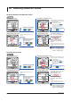
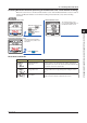
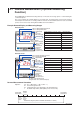
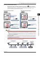
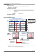
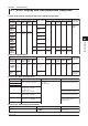
Table Of Contents
- Introduction
- Notices
- Checking the Package
- Checking the Model and Suffix Codes
- Contents
- Chapter 1 Installation and Wiring
- 1.1 Installation with the ANSI 4-inch Round Form or JIS 110-square Instrument Size
- 1.2 Installation with the DIN 96-square Instrument Size
- 1.3 Wiring
- Crimping Terminal Recommendations
- Single-phase two-wire system (voltage input, current input, power supply)
- Single-phase three-wire system (voltage input, current input, power supply)
- Three-phase three-wire system (voltage input, current input, power supply)
- Three-phase four-wire system (voltage input, current input, power supply)
- Three-phase four-wire system (2.5 element) (voltage input, current input, power supply)
- Other Wiring
- 1.4 Attaching the Dust Cover and Terminal Cover
- Chapter 2 Preparations before Starting Measurement (Set up the PR300 First)
- Chapter 3 Parameter Setting Operations
- 3.1 Basic Parameter Setting Operations
- 3.2 Setting the VT and CT Ratios
- 3.3 Setting the Integrated Low-cut Power
- 3.4 Setting RS-485 Communication Conditions
- 3.5 Setting Ethernet Communication Conditions
- 3.6 Setting Pulse Output Conditions
- 3.7 Setting Analog Output Conditions
- 3.8 Setting Demand Measurement Conditions
- 3.9 Setting the Measured Value Display Pattern
- 3.10 Setting the “Indicator-out” Mode and Locking Parameters
- Chapter 4 Operation for Display of Measurement Items and Measurement Method
- 4.1 Measurement Items
- 4.2 Switching Display Pattern
- 4.3 Displaying Measured, Instantaneous, and Maximum/Minimum Values
- Example Display and Measuring Ranges of Active Power (Regenerative Power)
- Example Display and Measuring Ranges of Reactive Power
- Example Display and Measuring Ranges of Apparent Power
- Example Display and Measuring Ranges of Voltage
- Example Display and Measuring Ranges of Current
- Example Display and Measuring Ranges of Power Factor
- Example Display and Measuring Ranges of Frequency
- How to Switch between Instantaneous Value, Maximum Value, and Minimum Value
- 4.4 Phase Switching for Voltage and Current
- 4.5 Displaying Energy Values
- 4.6 Resetting Measured Values
- 4.7 Demand Measurement (Optional Measuring Function)
- Chapter 5 Troubleshooting
- Appendix
- Appendix 1 Specifications of PR300
- Measuring Function
- Power Items and Equations
- Input Specifications
- Digital Input Specifications
- Analog Output Specifications (additional output function)
- Pulse Output Specifications (additional output function)
- Demand Alarm Output Specifications (optional measuring function)
- Communication Specifications
- Standard Performance
- Safety and EMC Standards
- Environmental Conditions
- Mounting and Shape
- Appendix 2 System Reset
- Appendix 3 Parameter Map
- Appendix 4 Parameter List
- Appendix 5 Alphanumeric Characters Table for 7-segment LED
- Appendix 1 Specifications of PR300
- Index
- A
- C
- D
- E
- H
- I
- M
- O
- P
- R
- S
- T
- V
- W
- Wiring diagram
- Single-phase two-wire system
- Single-phase three-wire system
- Three-phase three-wire system
- Three-phase four-wire system
- Three-phase four-wire system (2.5 element)
- Analog output
- Demand alarm output
- Demand alarm release
- Ethernet communication
- Integration control signal
- Palse output
- RS-485 communication
- Wiring diagram
4-14
IM 77C01E01-01E
4.7 Demand Measurement (Optional Measuring Function)
Demand Alarm
Demand alarm output
Function: When the set demand alarm point is exceeded, an alarm is output.
Output signal: Open collector
Output capacity: 30 V DC, 200 mA
Demand alarm release function
Automatic release: When the demand value falls below the demand alarm point, the alarm is canceled.
Manual release: The state of the alarm is maintained even if the demand value falls below the
demand alarm point. It is canceled via communication or by digital input or the
operation key.
Digital input Number of inputs: 1
ON signal: 4.5 to 25 V DC
OFF signal: within 1 V DC
Demand alarm mask time
The demand alarm mask time is the time between the beginning of the demand period and the set time,
during which a demand alarm is not recognized.
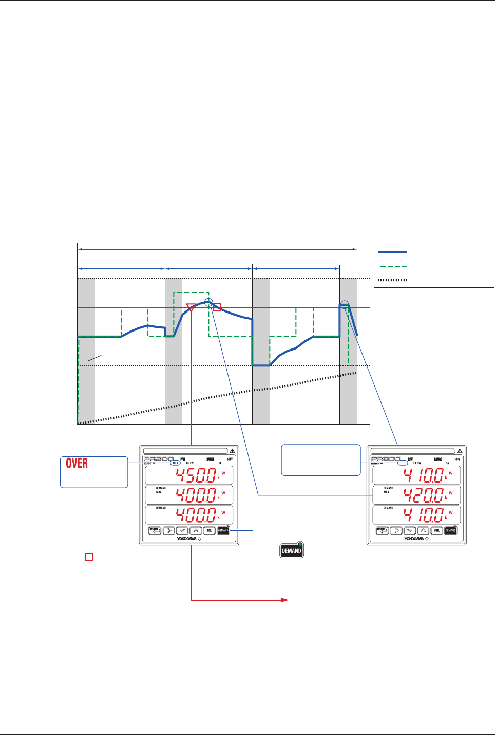
Example Demand Measurement
010 20 3230
100
200
300
400
500
(kW)
Demand period:
10 minutes
Demand period:
10 minutes
Demand period:
10 minutes
Demand measuring time: 32 minutes
(update interval: 10 seconds, times of measurement: 192)
Demand power
Demand alarm point
Demand alarm
mask time
Time (min)
Active power (kW)
Active energy (kWh)
Does not turn on
in the demand
alarm mask time.
turns on
during the
demand alarm.
Maximum demand value
Demand alarm output (open collector)
In conjunction with the demand alarm lamp, the
demand alarm output keeps sending an alarm until cancellation.
To manually cancel
the alarm,
press once or perform the
cancellation procedure via communication.
The alarm can be canceled by the operation key
or via communication regardless of the status
of the start/stop operation.
When the demand
alarm release function
is set to “Automatic
release,” the alarm is
automatically canceled
when the demand value
falls below the alarm
point.
Maximum demand value
The maximum demand value is the maximum value in the demand measuring time. This value is retained
until system reset or start of the next demand measurement.