
Energy Meter Manual
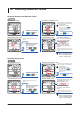
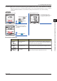
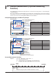
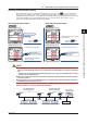
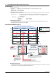
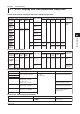
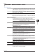
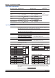
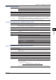
Table Of Contents
- Introduction
- Notices
- Checking the Package
- Checking the Model and Suffix Codes
- Contents
- Chapter 1 Installation and Wiring
- 1.1 Installation with the ANSI 4-inch Round Form or JIS 110-square Instrument Size
- 1.2 Installation with the DIN 96-square Instrument Size
- 1.3 Wiring
- Crimping Terminal Recommendations
- Single-phase two-wire system (voltage input, current input, power supply)
- Single-phase three-wire system (voltage input, current input, power supply)
- Three-phase three-wire system (voltage input, current input, power supply)
- Three-phase four-wire system (voltage input, current input, power supply)
- Three-phase four-wire system (2.5 element) (voltage input, current input, power supply)
- Other Wiring
- 1.4 Attaching the Dust Cover and Terminal Cover
- Chapter 2 Preparations before Starting Measurement (Set up the PR300 First)
- Chapter 3 Parameter Setting Operations
- 3.1 Basic Parameter Setting Operations
- 3.2 Setting the VT and CT Ratios
- 3.3 Setting the Integrated Low-cut Power
- 3.4 Setting RS-485 Communication Conditions
- 3.5 Setting Ethernet Communication Conditions
- 3.6 Setting Pulse Output Conditions
- 3.7 Setting Analog Output Conditions
- 3.8 Setting Demand Measurement Conditions
- 3.9 Setting the Measured Value Display Pattern
- 3.10 Setting the “Indicator-out” Mode and Locking Parameters
- Chapter 4 Operation for Display of Measurement Items and Measurement Method
- 4.1 Measurement Items
- 4.2 Switching Display Pattern
- 4.3 Displaying Measured, Instantaneous, and Maximum/Minimum Values
- Example Display and Measuring Ranges of Active Power (Regenerative Power)
- Example Display and Measuring Ranges of Reactive Power
- Example Display and Measuring Ranges of Apparent Power
- Example Display and Measuring Ranges of Voltage
- Example Display and Measuring Ranges of Current
- Example Display and Measuring Ranges of Power Factor
- Example Display and Measuring Ranges of Frequency
- How to Switch between Instantaneous Value, Maximum Value, and Minimum Value
- 4.4 Phase Switching for Voltage and Current
- 4.5 Displaying Energy Values
- 4.6 Resetting Measured Values
- 4.7 Demand Measurement (Optional Measuring Function)
- Chapter 5 Troubleshooting
- Appendix
- Appendix 1 Specifications of PR300
- Measuring Function
- Power Items and Equations
- Input Specifications
- Digital Input Specifications
- Analog Output Specifications (additional output function)
- Pulse Output Specifications (additional output function)
- Demand Alarm Output Specifications (optional measuring function)
- Communication Specifications
- Standard Performance
- Safety and EMC Standards
- Environmental Conditions
- Mounting and Shape
- Appendix 2 System Reset
- Appendix 3 Parameter Map
- Appendix 4 Parameter List
- Appendix 5 Alphanumeric Characters Table for 7-segment LED
- Appendix 1 Specifications of PR300
- Index
- A
- C
- D
- E
- H
- I
- M
- O
- P
- R
- S
- T
- V
- W
- Wiring diagram
- Single-phase two-wire system
- Single-phase three-wire system
- Three-phase three-wire system
- Three-phase four-wire system
- Three-phase four-wire system (2.5 element)
- Analog output
- Demand alarm output
- Demand alarm release
- Ethernet communication
- Integration control signal
- Palse output
- RS-485 communication
- Wiring diagram
4-10
IM 77C01E01-01E
4.6 Resetting Measured Values
Resetting Maximum and Minimum Values
Operation
Operation
Simultaneously hold down
and for at
least 5 seconds.
Measured Value screen
Measured Value screen
Reset Item Selection screen
Reset Item Confirmation screen
1
2
3
Press once.
The Reset Item Selection screen
appears.
The Reset Item Confirmation screen
appears, and the reset items blinks.
The maximum and minimum
values are reset, and the PR300
returns to the Measured Value
“RESET” appears for about 1
second, then a measured value
appears.
(“RESET” will not appear if returning to the screen
not showing the maximum or minimum value after
resetting.)
To return to the Measured
Value screen without resetting,
refer to “Canceling Reset Item
Selection” on the next page.
Reset items
Display the reset items on
the screen (refer to the
figure on the left)
using or
and press once.
To stop resetting
To change the reset items
Press any key other than while
the reset items are blinking.
The PR300 returns to the Reset Item
Selection screen.
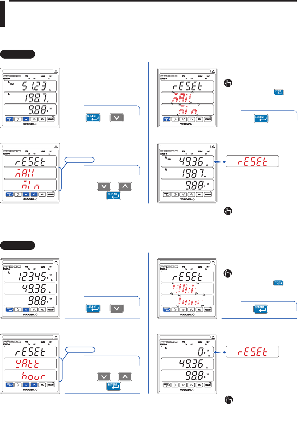
Resetting Energy Value
Operation
Operation
Measured Value screen
Measured Value screen
Reset Item Selection screen
Reset Item Confirmation screen
1
2
3
The Reset Item Selection screen
appears.
The energy value is reset, and
the PR300 returns to the
Measured Value screen.
Reset items
The Reset Item Confirmation screen
appears, and the reset items blinks.
“RESET” appears for about 1
second, then a measured value
appears.
(“RESET” will not appear if returning to the
screen not showing the energy value after
resetting.)
To return to the Measured
Value screen without resetting,
refer to “Canceling Reset Item
Selection” on the next page.
Simultaneously hold down
and for at
least 5 seconds.
Press once.
Display the reset items on
the screen (refer to the
figure on the left)
using or
and press once.
To stop resetting
To change the reset items
Press any key other than while
the reset items are blinking.
The PR300 returns to the Reset Item
Selection screen.