
Energy Meter Manual
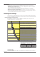
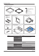
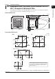

Table Of Contents
- Introduction
- Notices
- Checking the Package
- Checking the Model and Suffix Codes
- Contents
- Chapter 1 Installation and Wiring
- 1.1 Installation with the ANSI 4-inch Round Form or JIS 110-square Instrument Size
- 1.2 Installation with the DIN 96-square Instrument Size
- 1.3 Wiring
- Crimping Terminal Recommendations
- Single-phase two-wire system (voltage input, current input, power supply)
- Single-phase three-wire system (voltage input, current input, power supply)
- Three-phase three-wire system (voltage input, current input, power supply)
- Three-phase four-wire system (voltage input, current input, power supply)
- Three-phase four-wire system (2.5 element) (voltage input, current input, power supply)
- Other Wiring
- 1.4 Attaching the Dust Cover and Terminal Cover
- Chapter 2 Preparations before Starting Measurement (Set up the PR300 First)
- Chapter 3 Parameter Setting Operations
- 3.1 Basic Parameter Setting Operations
- 3.2 Setting the VT and CT Ratios
- 3.3 Setting the Integrated Low-cut Power
- 3.4 Setting RS-485 Communication Conditions
- 3.5 Setting Ethernet Communication Conditions
- 3.6 Setting Pulse Output Conditions
- 3.7 Setting Analog Output Conditions
- 3.8 Setting Demand Measurement Conditions
- 3.9 Setting the Measured Value Display Pattern
- 3.10 Setting the “Indicator-out” Mode and Locking Parameters
- Chapter 4 Operation for Display of Measurement Items and Measurement Method
- 4.1 Measurement Items
- 4.2 Switching Display Pattern
- 4.3 Displaying Measured, Instantaneous, and Maximum/Minimum Values
- Example Display and Measuring Ranges of Active Power (Regenerative Power)
- Example Display and Measuring Ranges of Reactive Power
- Example Display and Measuring Ranges of Apparent Power
- Example Display and Measuring Ranges of Voltage
- Example Display and Measuring Ranges of Current
- Example Display and Measuring Ranges of Power Factor
- Example Display and Measuring Ranges of Frequency
- How to Switch between Instantaneous Value, Maximum Value, and Minimum Value
- 4.4 Phase Switching for Voltage and Current
- 4.5 Displaying Energy Values
- 4.6 Resetting Measured Values
- 4.7 Demand Measurement (Optional Measuring Function)
- Chapter 5 Troubleshooting
- Appendix
- Appendix 1 Specifications of PR300
- Measuring Function
- Power Items and Equations
- Input Specifications
- Digital Input Specifications
- Analog Output Specifications (additional output function)
- Pulse Output Specifications (additional output function)
- Demand Alarm Output Specifications (optional measuring function)
- Communication Specifications
- Standard Performance
- Safety and EMC Standards
- Environmental Conditions
- Mounting and Shape
- Appendix 2 System Reset
- Appendix 3 Parameter Map
- Appendix 4 Parameter List
- Appendix 5 Alphanumeric Characters Table for 7-segment LED
- Appendix 1 Specifications of PR300
- Index
- A
- C
- D
- E
- H
- I
- M
- O
- P
- R
- S
- T
- V
- W
- Wiring diagram
- Single-phase two-wire system
- Single-phase three-wire system
- Three-phase three-wire system
- Three-phase four-wire system
- Three-phase four-wire system (2.5 element)
- Analog output
- Demand alarm output
- Demand alarm release
- Ethernet communication
- Integration control signal
- Palse output
- RS-485 communication
- Wiring diagram
iv
IM 77C01E01-01E
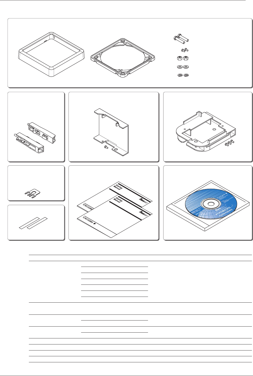
Checking the Accessories
M
ode
l P
R
300
P
o
w
er an
d E
n
e
rgy M
e
te
r
<
Initial S
etup O
p
eratio
ns>
M
o
del P
R
300
P
ow
er a
nd E
ne
rgy M
e
ter
<
Installation
>
(1) JIS/ANSI-mounting kit
Bezel
Panel-mounting bolts (2)
Nuts (2)
Flat washers (2)
Spring washers (2)
Bracket-fixing screws (2)
Panel-mounting bracket
(2) DIN-mounting
brackets
(5) Shorting bar
(6) Tag number labels
(7) Startup Manuals (8) Manuals for the PR300 (CD)
(for DIN 96-square
instrument panel
mounting)
(for RS-485 communication
termination)
(3) Dust cover
(with 1 fixing screw)
(Installation/Initial Setup Operations)
(4) Terminal cover
(with 3 fixing screws)
Item Name
(1) JIS/ANSI-mounting kit
(2) DIN-mounting brackets
(3) Dust cover
(4) Terminal cover
(5) Shorting bar
(6) Tag number label
(7) Startup manual
(8) Manuals for the PR300(CD)
Bezel
Panel-mounting bracket
Panel-mounting bolts
Bracket-fixing screws
Flat washers
Spring washers
Nuts
Fixing screw
Fixing screws
Remarks
Used to mount the PR300 according to the ANSI 4-inch round
form size or JIS110-square instrument size.
Used to mount the PR300 according to the DIN 96-square
instrument size.
Attached onto the top of the PR300 main unit.
Attached to the PR300 terminal section. (Must always be
attached to avoid a possible electric shock.)
Used in RS-485 communication if the
PR300
is a terminal device.
A quick reference manual for use in initial installation.
This CD contains all manuals related to the PR300.
Qty
1
1
2
2
2
2
2
2
1
1
1
3
1
2
2
1
Checking the Package