
Energy Meter Manual
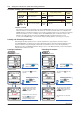
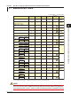
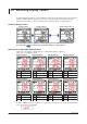
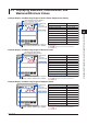
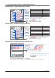
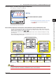
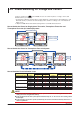
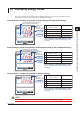
Table Of Contents
- Introduction
- Notices
- Checking the Package
- Checking the Model and Suffix Codes
- Contents
- Chapter 1 Installation and Wiring
- 1.1 Installation with the ANSI 4-inch Round Form or JIS 110-square Instrument Size
- 1.2 Installation with the DIN 96-square Instrument Size
- 1.3 Wiring
- Crimping Terminal Recommendations
- Single-phase two-wire system (voltage input, current input, power supply)
- Single-phase three-wire system (voltage input, current input, power supply)
- Three-phase three-wire system (voltage input, current input, power supply)
- Three-phase four-wire system (voltage input, current input, power supply)
- Three-phase four-wire system (2.5 element) (voltage input, current input, power supply)
- Other Wiring
- 1.4 Attaching the Dust Cover and Terminal Cover
- Chapter 2 Preparations before Starting Measurement (Set up the PR300 First)
- Chapter 3 Parameter Setting Operations
- 3.1 Basic Parameter Setting Operations
- 3.2 Setting the VT and CT Ratios
- 3.3 Setting the Integrated Low-cut Power
- 3.4 Setting RS-485 Communication Conditions
- 3.5 Setting Ethernet Communication Conditions
- 3.6 Setting Pulse Output Conditions
- 3.7 Setting Analog Output Conditions
- 3.8 Setting Demand Measurement Conditions
- 3.9 Setting the Measured Value Display Pattern
- 3.10 Setting the “Indicator-out” Mode and Locking Parameters
- Chapter 4 Operation for Display of Measurement Items and Measurement Method
- 4.1 Measurement Items
- 4.2 Switching Display Pattern
- 4.3 Displaying Measured, Instantaneous, and Maximum/Minimum Values
- Example Display and Measuring Ranges of Active Power (Regenerative Power)
- Example Display and Measuring Ranges of Reactive Power
- Example Display and Measuring Ranges of Apparent Power
- Example Display and Measuring Ranges of Voltage
- Example Display and Measuring Ranges of Current
- Example Display and Measuring Ranges of Power Factor
- Example Display and Measuring Ranges of Frequency
- How to Switch between Instantaneous Value, Maximum Value, and Minimum Value
- 4.4 Phase Switching for Voltage and Current
- 4.5 Displaying Energy Values
- 4.6 Resetting Measured Values
- 4.7 Demand Measurement (Optional Measuring Function)
- Chapter 5 Troubleshooting
- Appendix
- Appendix 1 Specifications of PR300
- Measuring Function
- Power Items and Equations
- Input Specifications
- Digital Input Specifications
- Analog Output Specifications (additional output function)
- Pulse Output Specifications (additional output function)
- Demand Alarm Output Specifications (optional measuring function)
- Communication Specifications
- Standard Performance
- Safety and EMC Standards
- Environmental Conditions
- Mounting and Shape
- Appendix 2 System Reset
- Appendix 3 Parameter Map
- Appendix 4 Parameter List
- Appendix 5 Alphanumeric Characters Table for 7-segment LED
- Appendix 1 Specifications of PR300
- Index
- A
- C
- D
- E
- H
- I
- M
- O
- P
- R
- S
- T
- V
- W
- Wiring diagram
- Single-phase two-wire system
- Single-phase three-wire system
- Three-phase three-wire system
- Three-phase four-wire system
- Three-phase four-wire system (2.5 element)
- Analog output
- Demand alarm output
- Demand alarm release
- Ethernet communication
- Integration control signal
- Palse output
- RS-485 communication
- Wiring diagram
4-2
IM 77C01E01-01E
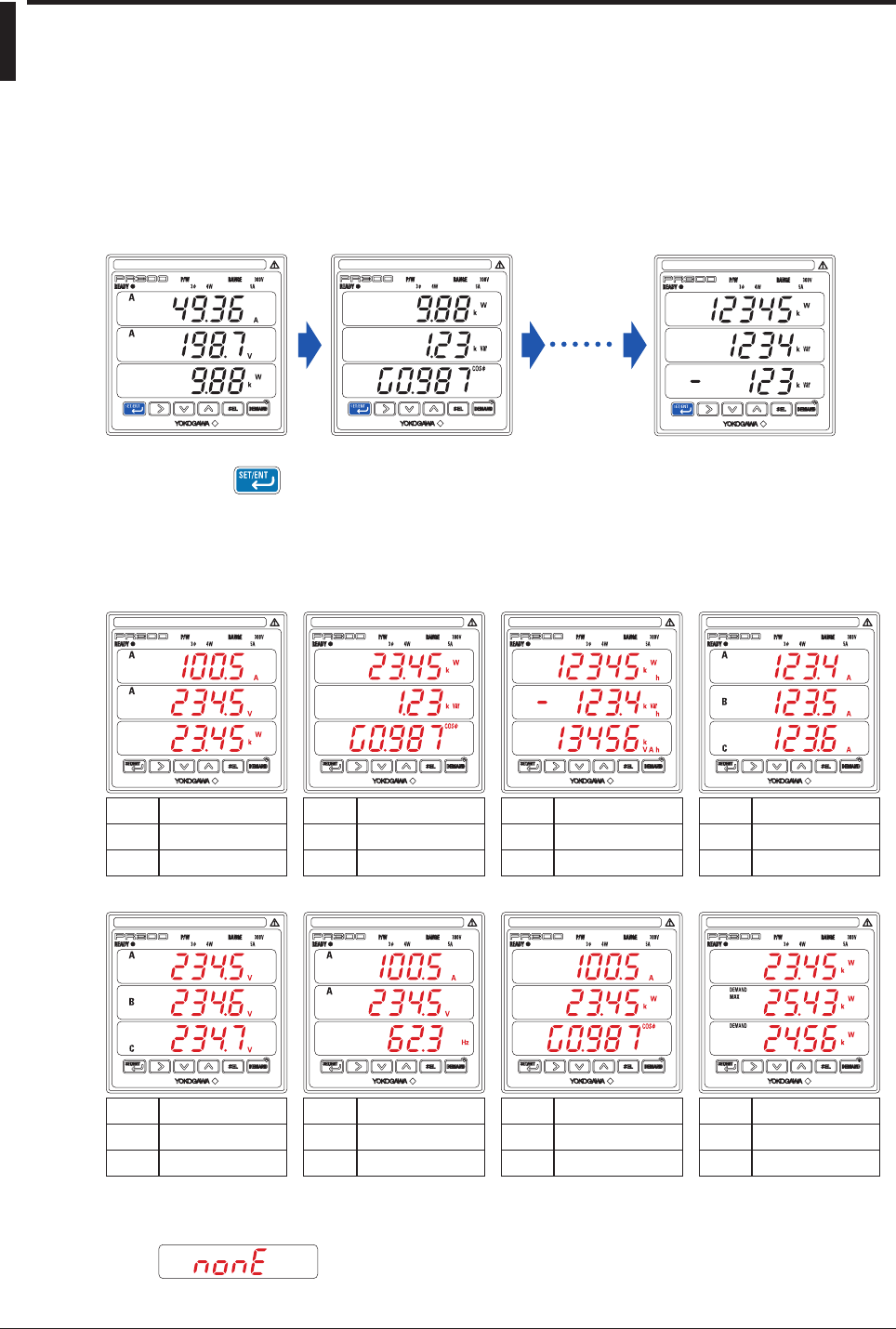
4.2 Switching Display Pattern
According to Display patterns-1 to 8, the PR300 can change the measurement items to be assigned to
the upper, middle, and lower displays (refer to Section 3.9, “Setting the Measured Value Display
Pattern”). The procedure to change the display pattern and initial values are explained below.
Switching Display Pattern
The initial value is “Display pattern-1,” and the display pattern number will be incremented
by 1 every time is pressed. After the number reaches n, it will return to 1.
Display pattern-1 Display pattern-2 Display pattern-n (up to 8)
Initial Values and Example Display Patterns
Initial value of the number of display patterns: 1 (Only display pattern-1 appears.)
Initial value of each display pattern:
Upper
display
Middle
display
Lower
display
Current
(phase switch indication)
Voltage
(phase switch indication)
Active power
Upper
display
Middle
display
Lower
display
Active power
Reactive power
Power factor
Upper
display
Middle
display
Lower
display
Active energy
LEAD reactive energy
Apparent energy
Upper
display
Middle
display
Lower
display
Current-1
Current-2
Current-3
Upper
display
Middle
display
Lower
display
Voltage-1
Voltage-2
Voltage-3
Upper
display
Middle
display
Lower
display
Current
(phase switch indication)
Voltage
(phase switch indication)
Frequency
Upper
display
Middle
display
Lower
display
Current
(phase switch indication)
Active power
Power factor
Upper
display
Middle
display
Lower
display
Active power
Maximum demand value
Demand value
Display pattern-1 Display pattern-2 Display pattern-3 Display pattern-4
Display pattern-5 Display pattern-6 Display pattern-7 Display pattern-8
As below, “NONE” appears in the display of a measurement item whose value cannot be displayed due
to the specifications of the PR300.