
Energy Meter Manual
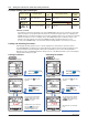
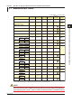
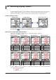
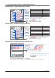
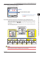
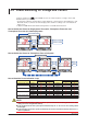
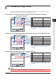
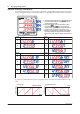
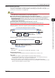
Table Of Contents
- Introduction
- Notices
- Checking the Package
- Checking the Model and Suffix Codes
- Contents
- Chapter 1 Installation and Wiring
- 1.1 Installation with the ANSI 4-inch Round Form or JIS 110-square Instrument Size
- 1.2 Installation with the DIN 96-square Instrument Size
- 1.3 Wiring
- Crimping Terminal Recommendations
- Single-phase two-wire system (voltage input, current input, power supply)
- Single-phase three-wire system (voltage input, current input, power supply)
- Three-phase three-wire system (voltage input, current input, power supply)
- Three-phase four-wire system (voltage input, current input, power supply)
- Three-phase four-wire system (2.5 element) (voltage input, current input, power supply)
- Other Wiring
- 1.4 Attaching the Dust Cover and Terminal Cover
- Chapter 2 Preparations before Starting Measurement (Set up the PR300 First)
- Chapter 3 Parameter Setting Operations
- 3.1 Basic Parameter Setting Operations
- 3.2 Setting the VT and CT Ratios
- 3.3 Setting the Integrated Low-cut Power
- 3.4 Setting RS-485 Communication Conditions
- 3.5 Setting Ethernet Communication Conditions
- 3.6 Setting Pulse Output Conditions
- 3.7 Setting Analog Output Conditions
- 3.8 Setting Demand Measurement Conditions
- 3.9 Setting the Measured Value Display Pattern
- 3.10 Setting the “Indicator-out” Mode and Locking Parameters
- Chapter 4 Operation for Display of Measurement Items and Measurement Method
- 4.1 Measurement Items
- 4.2 Switching Display Pattern
- 4.3 Displaying Measured, Instantaneous, and Maximum/Minimum Values
- Example Display and Measuring Ranges of Active Power (Regenerative Power)
- Example Display and Measuring Ranges of Reactive Power
- Example Display and Measuring Ranges of Apparent Power
- Example Display and Measuring Ranges of Voltage
- Example Display and Measuring Ranges of Current
- Example Display and Measuring Ranges of Power Factor
- Example Display and Measuring Ranges of Frequency
- How to Switch between Instantaneous Value, Maximum Value, and Minimum Value
- 4.4 Phase Switching for Voltage and Current
- 4.5 Displaying Energy Values
- 4.6 Resetting Measured Values
- 4.7 Demand Measurement (Optional Measuring Function)
- Chapter 5 Troubleshooting
- Appendix
- Appendix 1 Specifications of PR300
- Measuring Function
- Power Items and Equations
- Input Specifications
- Digital Input Specifications
- Analog Output Specifications (additional output function)
- Pulse Output Specifications (additional output function)
- Demand Alarm Output Specifications (optional measuring function)
- Communication Specifications
- Standard Performance
- Safety and EMC Standards
- Environmental Conditions
- Mounting and Shape
- Appendix 2 System Reset
- Appendix 3 Parameter Map
- Appendix 4 Parameter List
- Appendix 5 Alphanumeric Characters Table for 7-segment LED
- Appendix 1 Specifications of PR300
- Index
- A
- C
- D
- E
- H
- I
- M
- O
- P
- R
- S
- T
- V
- W
- Wiring diagram
- Single-phase two-wire system
- Single-phase three-wire system
- Three-phase three-wire system
- Three-phase four-wire system
- Three-phase four-wire system (2.5 element)
- Analog output
- Demand alarm output
- Demand alarm release
- Ethernet communication
- Integration control signal
- Palse output
- RS-485 communication
- Wiring diagram
3-20
IM 77C01E01-01E
3.10 Setting the “Indicator-out” Mode and Locking Parameters
Parameter Setting Types and Ranges
Display setting menu
Indicator-out mode
Indicator-out mode wait time
Selection
Integral
numeric
value
ON
OFF
1 to 60 (min)
OFF
10 (min)
Menu to shift to the parameters of
display setting
Parameter Symbol Parameter Name
Setting
Type
Setting Range (Details)
Initial Value
(Factory-set
Value)
Indicator-out mode
The indicator-out mode is designed to turn off the PR300 display when no key operation is performed
within the indicator-out mode wait time that has been set while measured values are on display. The
PR300 switches to the Measured Value screen in about 5 minutes when no key operation is performed
while the Parameter screen is on display. Then, the PR300 display turns off after the elapse of the
indicator-out mode wait time from when the PR300 switched to the Measured Value screen.
To turn on the PR300 display to show measured values during indicator-out mode, press any key.
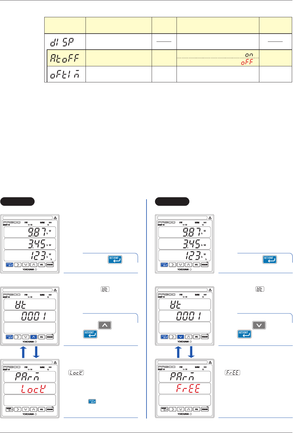
Locking and Unlocking Parameters
Executing the following operations locks or unlocks all parameters. (A parameter cannot be locked or
unlocked individually.) If a parameter is locked, it will be impossible to shift to the Parameter Setting screen.
Use the Parameter screen showing the current value or the Menu screen to lock or unlock parameters.
Operations used on an individual parameter setting screen or on the Measured Value screen in an attempt to
lock parameters will have no effect.
Operation
Operation
Operation
Operation
The measured value display
(middle display) first shows
, then returns to the
Parameter screen.
VT Ratio screen
2
All parameters are locked now.
Pressing will no longer
switch the display to any
parameter setting screen.
The measured value display
(middle display) first shows
, then returns to the
Parameter screen.
All parameters are unlocked
now.
Simultaneously hold
down and
for at least 5
seconds.
Measured Value screen
1
Measured Value screen
1
The parameter (VT ratio)
appears.
VT Ratio screen
2
Simultaneously hold
down and
for at least 5
seconds.
The parameter (VT ratio)
appears.
Hold down for at
least 3 seconds.
Hold down for at
least 3 seconds.
Unlocking ParametersLocking Parameters