
Energy Meter Manual
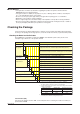
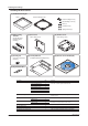
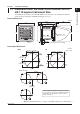

Table Of Contents
- Introduction
- Notices
- Checking the Package
- Checking the Model and Suffix Codes
- Contents
- Chapter 1 Installation and Wiring
- 1.1 Installation with the ANSI 4-inch Round Form or JIS 110-square Instrument Size
- 1.2 Installation with the DIN 96-square Instrument Size
- 1.3 Wiring
- Crimping Terminal Recommendations
- Single-phase two-wire system (voltage input, current input, power supply)
- Single-phase three-wire system (voltage input, current input, power supply)
- Three-phase three-wire system (voltage input, current input, power supply)
- Three-phase four-wire system (voltage input, current input, power supply)
- Three-phase four-wire system (2.5 element) (voltage input, current input, power supply)
- Other Wiring
- 1.4 Attaching the Dust Cover and Terminal Cover
- Chapter 2 Preparations before Starting Measurement (Set up the PR300 First)
- Chapter 3 Parameter Setting Operations
- 3.1 Basic Parameter Setting Operations
- 3.2 Setting the VT and CT Ratios
- 3.3 Setting the Integrated Low-cut Power
- 3.4 Setting RS-485 Communication Conditions
- 3.5 Setting Ethernet Communication Conditions
- 3.6 Setting Pulse Output Conditions
- 3.7 Setting Analog Output Conditions
- 3.8 Setting Demand Measurement Conditions
- 3.9 Setting the Measured Value Display Pattern
- 3.10 Setting the “Indicator-out” Mode and Locking Parameters
- Chapter 4 Operation for Display of Measurement Items and Measurement Method
- 4.1 Measurement Items
- 4.2 Switching Display Pattern
- 4.3 Displaying Measured, Instantaneous, and Maximum/Minimum Values
- Example Display and Measuring Ranges of Active Power (Regenerative Power)
- Example Display and Measuring Ranges of Reactive Power
- Example Display and Measuring Ranges of Apparent Power
- Example Display and Measuring Ranges of Voltage
- Example Display and Measuring Ranges of Current
- Example Display and Measuring Ranges of Power Factor
- Example Display and Measuring Ranges of Frequency
- How to Switch between Instantaneous Value, Maximum Value, and Minimum Value
- 4.4 Phase Switching for Voltage and Current
- 4.5 Displaying Energy Values
- 4.6 Resetting Measured Values
- 4.7 Demand Measurement (Optional Measuring Function)
- Chapter 5 Troubleshooting
- Appendix
- Appendix 1 Specifications of PR300
- Measuring Function
- Power Items and Equations
- Input Specifications
- Digital Input Specifications
- Analog Output Specifications (additional output function)
- Pulse Output Specifications (additional output function)
- Demand Alarm Output Specifications (optional measuring function)
- Communication Specifications
- Standard Performance
- Safety and EMC Standards
- Environmental Conditions
- Mounting and Shape
- Appendix 2 System Reset
- Appendix 3 Parameter Map
- Appendix 4 Parameter List
- Appendix 5 Alphanumeric Characters Table for 7-segment LED
- Appendix 1 Specifications of PR300
- Index
- A
- C
- D
- E
- H
- I
- M
- O
- P
- R
- S
- T
- V
- W
- Wiring diagram
- Single-phase two-wire system
- Single-phase three-wire system
- Three-phase three-wire system
- Three-phase four-wire system
- Three-phase four-wire system (2.5 element)
- Analog output
- Demand alarm output
- Demand alarm release
- Ethernet communication
- Integration control signal
- Palse output
- RS-485 communication
- Wiring diagram
iii
IM 77C01E01-01E
■Force Majeure
• Yokogawa does not make any warranties regarding the product except those mentioned in the
WARRANTY that is provided separately.
• Yokogawa assumes no liability to any party for any loss or damage, direct or indirect, caused by the
use or any unpredictable defect of the product.
• Be sure to use the spare parts approved by Yokogawa when replacing parts or consumables.
• Modification of the product is strictly prohibited.
• Reverse engineering such as the disassembly or decompilation of the product is strictly prohibited.
• No portion of the product supplied by Yokogawa may be transferred, exchanged, leased, or sublet for
use by any third party without the prior permission of Yokogawa.
Checking the Package
Verify the package as explained below before starting to use the product. Should the delivered product
be wrong or the package be missing any item, contact the vendor from which you purchased the product.
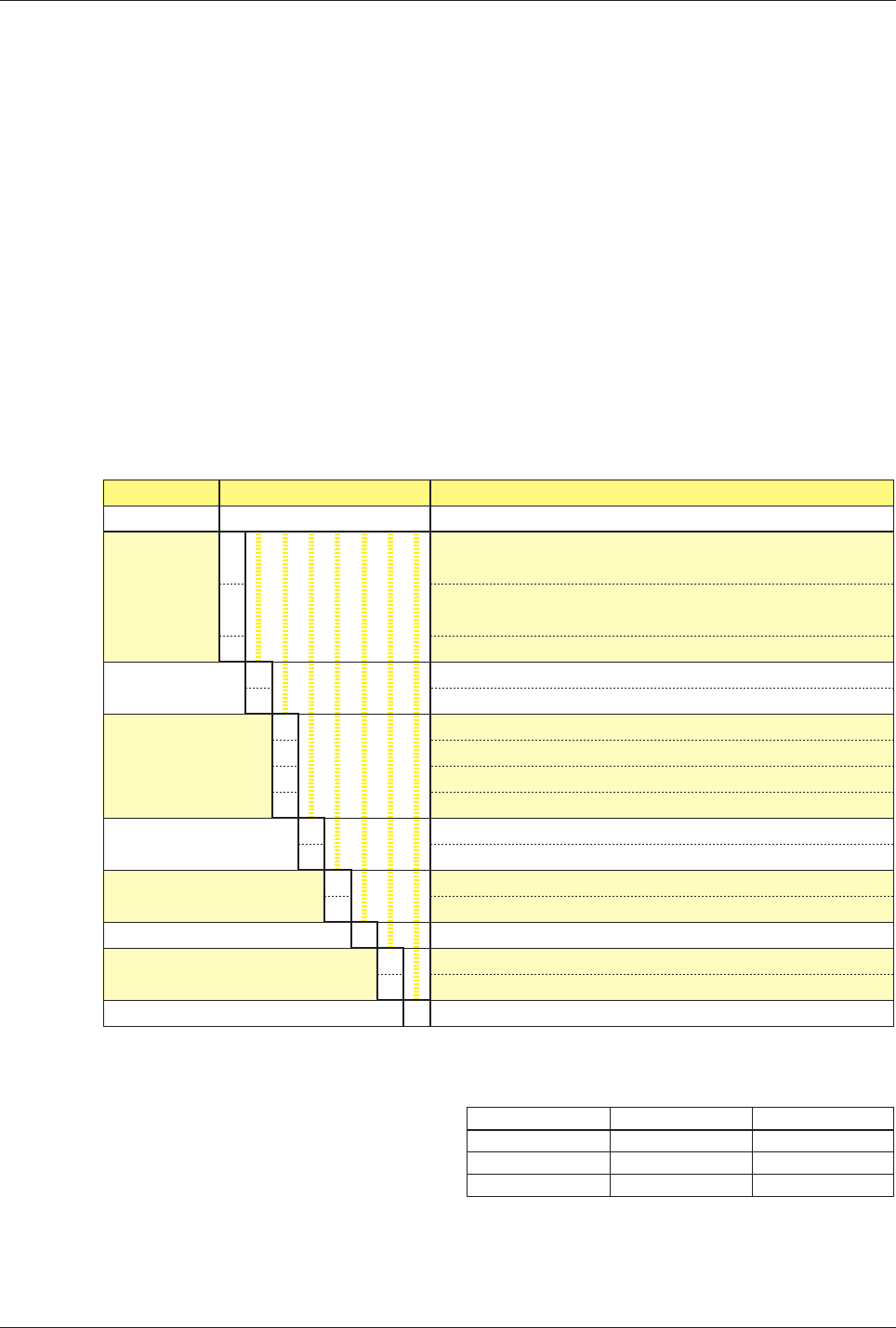
Checking the Model and Suffix Codes
The PR300 bears a nameplate. Confirm that “MODEL” and “SUFFIX” (suffix codes) shown on the
nameplate agree with those of the product ordered.
Model
PR300
Phase and
wire system
Input voltage/
input current
Additional input and
output function
Communication function
Optional measuring function
Power supply
Phase indication format
Suffix Codes
-ⵧ ⵧ ⵧ ⵧ ⵧ -6 ⵧ -0
-3
-4
-5
1
2
0
1
2
3
0
3
0
3
-6
A
R
-0
Description
Power and Energy Meter
Universal three-phase three-wire system (single-phase two-wire,
single-phase three-wire, and three-phase three-wire systems)
Universal three-phase four-wire system (
single-phase two-wire, single-
phase three-wire, three-phase three-wire, and three-phase four-wire systems
)
Three-phase four-wire system (2.5 element)
*1
Universal voltage input
*2
(150 V, 300 V, 600 V) / 1 A
Universal voltage input
*2
(150 V, 300 V, 600 V) / 5 A
1 digital input
1 digital input, 1 analog output
1 digital input, 1 pulse output
1 digital input, 1 analog output, 1 pulse output
RS-485 communication
RS-485 communication, Ethernet communication
*3
None
Demand measurement (1 demand alarm output)
100-240 V AC ±10% (50/60 Hz) or 130-300 V DC ±15%
A, B, and C indications
R, S, and T indications
Always 0
*1 Can be used only when the voltage is in a state of equilibrium.
In cases where “Three-phase four-wire system (2.5 element)” is specified,
the input current specification of 1 A AC is not applicable.
*2 Set the voltage range (150 V, 300 V or 600 V) according to the rated input
voltage to be measured.
*3 For Ethernet communication, the RS-485 communication interface is
exclusively for the Ethernet-serial gateway function.
Rated input voltage
120 V
240 V
480 V
Voltage range
150 V
300 V
600 V
Allowable input voltage
150 V
300 V
600 V
Serial Number (NO.)
Also inform this number shown in “NO.” on the nameplate when contacting the vendor from which you
purchased the PR300.