
Energy Meter Manual
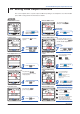
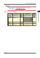
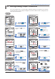
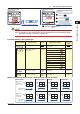
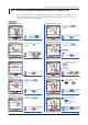
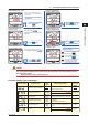
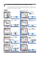
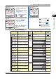
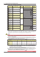
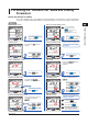
Table Of Contents
- Introduction
- Notices
- Checking the Package
- Checking the Model and Suffix Codes
- Contents
- Chapter 1 Installation and Wiring
- 1.1 Installation with the ANSI 4-inch Round Form or JIS 110-square Instrument Size
- 1.2 Installation with the DIN 96-square Instrument Size
- 1.3 Wiring
- Crimping Terminal Recommendations
- Single-phase two-wire system (voltage input, current input, power supply)
- Single-phase three-wire system (voltage input, current input, power supply)
- Three-phase three-wire system (voltage input, current input, power supply)
- Three-phase four-wire system (voltage input, current input, power supply)
- Three-phase four-wire system (2.5 element) (voltage input, current input, power supply)
- Other Wiring
- 1.4 Attaching the Dust Cover and Terminal Cover
- Chapter 2 Preparations before Starting Measurement (Set up the PR300 First)
- Chapter 3 Parameter Setting Operations
- 3.1 Basic Parameter Setting Operations
- 3.2 Setting the VT and CT Ratios
- 3.3 Setting the Integrated Low-cut Power
- 3.4 Setting RS-485 Communication Conditions
- 3.5 Setting Ethernet Communication Conditions
- 3.6 Setting Pulse Output Conditions
- 3.7 Setting Analog Output Conditions
- 3.8 Setting Demand Measurement Conditions
- 3.9 Setting the Measured Value Display Pattern
- 3.10 Setting the “Indicator-out” Mode and Locking Parameters
- Chapter 4 Operation for Display of Measurement Items and Measurement Method
- 4.1 Measurement Items
- 4.2 Switching Display Pattern
- 4.3 Displaying Measured, Instantaneous, and Maximum/Minimum Values
- Example Display and Measuring Ranges of Active Power (Regenerative Power)
- Example Display and Measuring Ranges of Reactive Power
- Example Display and Measuring Ranges of Apparent Power
- Example Display and Measuring Ranges of Voltage
- Example Display and Measuring Ranges of Current
- Example Display and Measuring Ranges of Power Factor
- Example Display and Measuring Ranges of Frequency
- How to Switch between Instantaneous Value, Maximum Value, and Minimum Value
- 4.4 Phase Switching for Voltage and Current
- 4.5 Displaying Energy Values
- 4.6 Resetting Measured Values
- 4.7 Demand Measurement (Optional Measuring Function)
- Chapter 5 Troubleshooting
- Appendix
- Appendix 1 Specifications of PR300
- Measuring Function
- Power Items and Equations
- Input Specifications
- Digital Input Specifications
- Analog Output Specifications (additional output function)
- Pulse Output Specifications (additional output function)
- Demand Alarm Output Specifications (optional measuring function)
- Communication Specifications
- Standard Performance
- Safety and EMC Standards
- Environmental Conditions
- Mounting and Shape
- Appendix 2 System Reset
- Appendix 3 Parameter Map
- Appendix 4 Parameter List
- Appendix 5 Alphanumeric Characters Table for 7-segment LED
- Appendix 1 Specifications of PR300
- Index
- A
- C
- D
- E
- H
- I
- M
- O
- P
- R
- S
- T
- V
- W
- Wiring diagram
- Single-phase two-wire system
- Single-phase three-wire system
- Three-phase three-wire system
- Three-phase four-wire system
- Three-phase four-wire system (2.5 element)
- Analog output
- Demand alarm output
- Demand alarm release
- Ethernet communication
- Integration control signal
- Palse output
- RS-485 communication
- Wiring diagram
Parameter Setting Operations
3-17
IM 77C01E01-01E
1
2
3
4
5
A
I
3.9 Setting the Measured Value Display Pattern
Display Pattern-1 Upper
Display screen
Display Pattern-1 Middle
Display screen
Refer to steps
8, 9
and
10
to also set other display
patterns.
11
Display Pattern-1 Lower
Display screen
To return to the Display Setting
Menu screen, press .
The parameter
(display pattern-1 middle
display) appears.
Press once.
The setpoint is confirmed and the PR300
returns to the Display Pattern-1 Upper
Display screen.
Display pattern-1 upper display
setting completed.
To return to the Measured Value
screen, hold down .
If you do not operate any key for more
than 5 minutes on the Parameter
screen, the PR300 automatically
returns to the Measured Value screen.
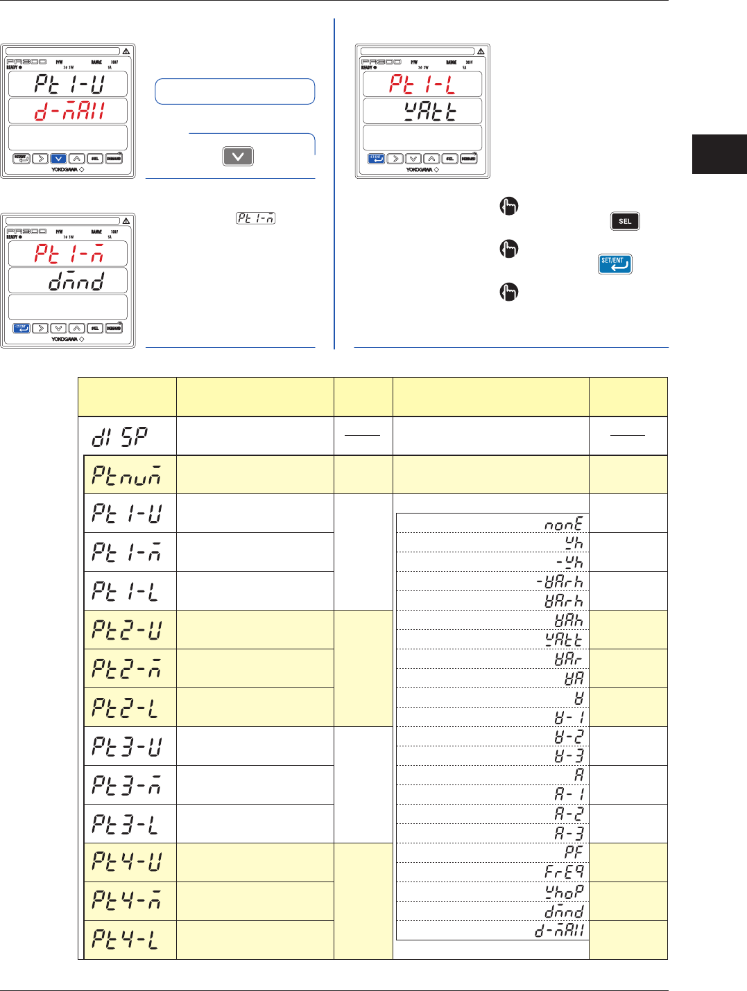
Parameter Setting Types and Ranges
Display setting menu
Number of display patterns
Display pattern-1 upper display
Display pattern-1 middle display
Display pattern-1 lower display
Display pattern-2 upper display
Display pattern-2 middle display
Display pattern-2 lower display
Display pattern-3 upper display
Display pattern-3 middle display
Display pattern-3 lower display
Display pattern-4 upper display
Display pattern-4 middle display
Display pattern-4 lower display
Integral
numeric
value
Selection
Selection
Selection
Selection
1 to 8
A measurement item can be selected from the
following:
None
Active energy
Regenerative energy
LEAD reactive energy
LAG reactive energy
Apparent energy
Active power
Reactive power
Apparent power
Voltage (phase switch inidication)
Voltage-1
Voltage-2
Voltage-3
Current (phase switch inidication)
Current-1
Current-2
Current-3
Power factor
Frequency
Optional active energy
Demand value
Maximum demand value
1
Voltage
(phase switch
inidication)
Active power
Active power
Reactive power
Power factor
Active energy
LEAD reactive
energy
Apparent
energy
Current
(phase switch
inidication)
Current-2
Current-3
Current-1
- Continued to next page -
Menu to shift to the parameters of
display setting
Parameter Symbol Parameter Name
Setting
Type
Setting Range (Details)
Initial Value
(Factory-set
Value)