
Energy Meter Manual
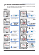
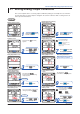
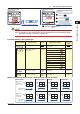
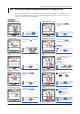
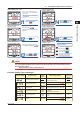
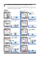
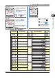
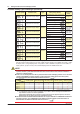
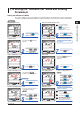
Table Of Contents
- Introduction
- Notices
- Checking the Package
- Checking the Model and Suffix Codes
- Contents
- Chapter 1 Installation and Wiring
- 1.1 Installation with the ANSI 4-inch Round Form or JIS 110-square Instrument Size
- 1.2 Installation with the DIN 96-square Instrument Size
- 1.3 Wiring
- Crimping Terminal Recommendations
- Single-phase two-wire system (voltage input, current input, power supply)
- Single-phase three-wire system (voltage input, current input, power supply)
- Three-phase three-wire system (voltage input, current input, power supply)
- Three-phase four-wire system (voltage input, current input, power supply)
- Three-phase four-wire system (2.5 element) (voltage input, current input, power supply)
- Other Wiring
- 1.4 Attaching the Dust Cover and Terminal Cover
- Chapter 2 Preparations before Starting Measurement (Set up the PR300 First)
- Chapter 3 Parameter Setting Operations
- 3.1 Basic Parameter Setting Operations
- 3.2 Setting the VT and CT Ratios
- 3.3 Setting the Integrated Low-cut Power
- 3.4 Setting RS-485 Communication Conditions
- 3.5 Setting Ethernet Communication Conditions
- 3.6 Setting Pulse Output Conditions
- 3.7 Setting Analog Output Conditions
- 3.8 Setting Demand Measurement Conditions
- 3.9 Setting the Measured Value Display Pattern
- 3.10 Setting the “Indicator-out” Mode and Locking Parameters
- Chapter 4 Operation for Display of Measurement Items and Measurement Method
- 4.1 Measurement Items
- 4.2 Switching Display Pattern
- 4.3 Displaying Measured, Instantaneous, and Maximum/Minimum Values
- Example Display and Measuring Ranges of Active Power (Regenerative Power)
- Example Display and Measuring Ranges of Reactive Power
- Example Display and Measuring Ranges of Apparent Power
- Example Display and Measuring Ranges of Voltage
- Example Display and Measuring Ranges of Current
- Example Display and Measuring Ranges of Power Factor
- Example Display and Measuring Ranges of Frequency
- How to Switch between Instantaneous Value, Maximum Value, and Minimum Value
- 4.4 Phase Switching for Voltage and Current
- 4.5 Displaying Energy Values
- 4.6 Resetting Measured Values
- 4.7 Demand Measurement (Optional Measuring Function)
- Chapter 5 Troubleshooting
- Appendix
- Appendix 1 Specifications of PR300
- Measuring Function
- Power Items and Equations
- Input Specifications
- Digital Input Specifications
- Analog Output Specifications (additional output function)
- Pulse Output Specifications (additional output function)
- Demand Alarm Output Specifications (optional measuring function)
- Communication Specifications
- Standard Performance
- Safety and EMC Standards
- Environmental Conditions
- Mounting and Shape
- Appendix 2 System Reset
- Appendix 3 Parameter Map
- Appendix 4 Parameter List
- Appendix 5 Alphanumeric Characters Table for 7-segment LED
- Appendix 1 Specifications of PR300
- Index
- A
- C
- D
- E
- H
- I
- M
- O
- P
- R
- S
- T
- V
- W
- Wiring diagram
- Single-phase two-wire system
- Single-phase three-wire system
- Three-phase three-wire system
- Three-phase four-wire system
- Three-phase four-wire system (2.5 element)
- Analog output
- Demand alarm output
- Demand alarm release
- Ethernet communication
- Integration control signal
- Palse output
- RS-485 communication
- Wiring diagram
3-10
IM 77C01E01-01E
For the PR300 with pulse output function only
3.6 Setting Pulse Output Conditions
This section explains how to set pulse output conditions by taking as an example the case when the ON
pulse width is changed from the initial value to 100 ms.
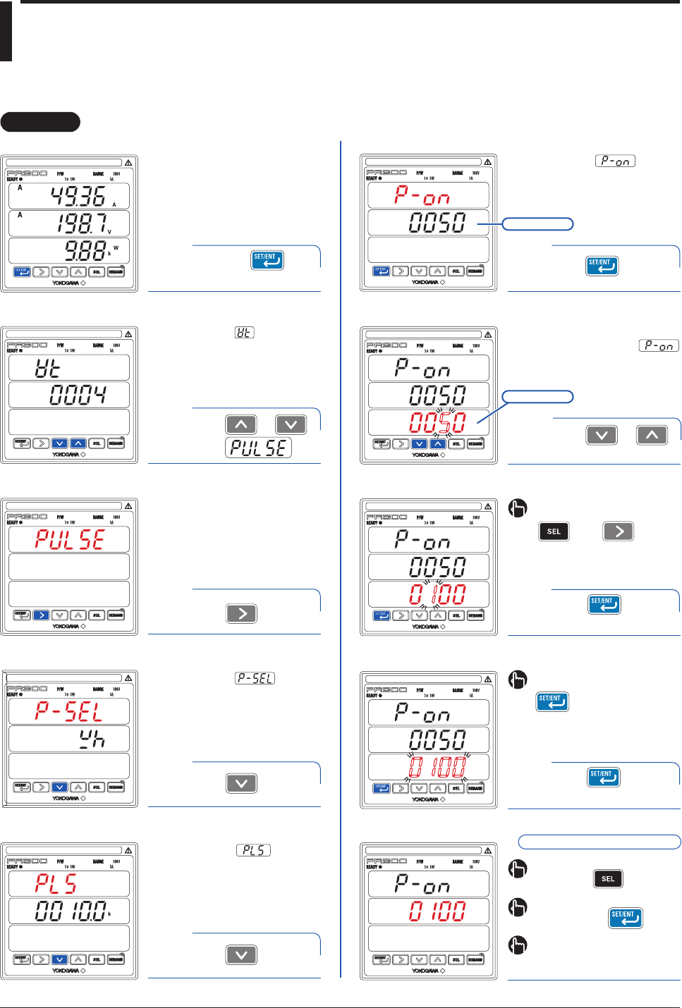
Operation
Operation
3
6
7
5
8
ON Pulse Width Setting
screen
ON Pulse Width screen
To return to the Pulse Output Menu
screen, press .
Current value
VT Ratio screen
2
Pulse Output Menu screen
Measurement
Item for Pulse Output screen
4
ON Pulse Width Setting
screen
ON Pulse Width Setting screen
Measured Value screen
1
The parameter (VT ratio)
appears.
Press once.
Press once.
The parameter
(measurement item for pulse
output) appears.
Pulse Unit screen
The parameter
(pulse unit) appears.
The screen changes to the one
for setting the parameter
and the alterable digit blinks.
ON Pulse Width screen
The parameter
(ON pulse width) appears.
Press once.
Setpoint
Hold down for at
least 3 seconds.
Press once.
Using or ,
change the setpoint.
Using or ,
show .
To return to the Measured Value
screen, hold down .
If you do not operate any key for more
than 5 minutes on the Parameter
screen, the PR300 automatically
returns to the Measured Value screen.
To move to the digit to be changed,
use the following keys:
To the left To the right
To re-set the parameter:
Press any key other than
while all digits of the
setpoint are blinking.
The PR300 returns to the initial
setting screen.
9
Press once to
blink the setpoint.
Press once while
the setpoint is blinking.
The setpoint is confirmed and the PR300
returns to the ON Pulse Width screen.
ON pulse width setting completed.