
Energy Meter Manual
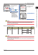
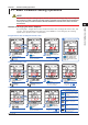
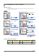
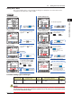
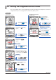
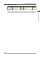
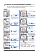
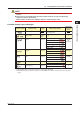
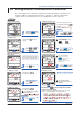
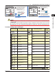
Table Of Contents
- Introduction
- Notices
- Checking the Package
- Checking the Model and Suffix Codes
- Contents
- Chapter 1 Installation and Wiring
- 1.1 Installation with the ANSI 4-inch Round Form or JIS 110-square Instrument Size
- 1.2 Installation with the DIN 96-square Instrument Size
- 1.3 Wiring
- Crimping Terminal Recommendations
- Single-phase two-wire system (voltage input, current input, power supply)
- Single-phase three-wire system (voltage input, current input, power supply)
- Three-phase three-wire system (voltage input, current input, power supply)
- Three-phase four-wire system (voltage input, current input, power supply)
- Three-phase four-wire system (2.5 element) (voltage input, current input, power supply)
- Other Wiring
- 1.4 Attaching the Dust Cover and Terminal Cover
- Chapter 2 Preparations before Starting Measurement (Set up the PR300 First)
- Chapter 3 Parameter Setting Operations
- 3.1 Basic Parameter Setting Operations
- 3.2 Setting the VT and CT Ratios
- 3.3 Setting the Integrated Low-cut Power
- 3.4 Setting RS-485 Communication Conditions
- 3.5 Setting Ethernet Communication Conditions
- 3.6 Setting Pulse Output Conditions
- 3.7 Setting Analog Output Conditions
- 3.8 Setting Demand Measurement Conditions
- 3.9 Setting the Measured Value Display Pattern
- 3.10 Setting the “Indicator-out” Mode and Locking Parameters
- Chapter 4 Operation for Display of Measurement Items and Measurement Method
- 4.1 Measurement Items
- 4.2 Switching Display Pattern
- 4.3 Displaying Measured, Instantaneous, and Maximum/Minimum Values
- Example Display and Measuring Ranges of Active Power (Regenerative Power)
- Example Display and Measuring Ranges of Reactive Power
- Example Display and Measuring Ranges of Apparent Power
- Example Display and Measuring Ranges of Voltage
- Example Display and Measuring Ranges of Current
- Example Display and Measuring Ranges of Power Factor
- Example Display and Measuring Ranges of Frequency
- How to Switch between Instantaneous Value, Maximum Value, and Minimum Value
- 4.4 Phase Switching for Voltage and Current
- 4.5 Displaying Energy Values
- 4.6 Resetting Measured Values
- 4.7 Demand Measurement (Optional Measuring Function)
- Chapter 5 Troubleshooting
- Appendix
- Appendix 1 Specifications of PR300
- Measuring Function
- Power Items and Equations
- Input Specifications
- Digital Input Specifications
- Analog Output Specifications (additional output function)
- Pulse Output Specifications (additional output function)
- Demand Alarm Output Specifications (optional measuring function)
- Communication Specifications
- Standard Performance
- Safety and EMC Standards
- Environmental Conditions
- Mounting and Shape
- Appendix 2 System Reset
- Appendix 3 Parameter Map
- Appendix 4 Parameter List
- Appendix 5 Alphanumeric Characters Table for 7-segment LED
- Appendix 1 Specifications of PR300
- Index
- A
- C
- D
- E
- H
- I
- M
- O
- P
- R
- S
- T
- V
- W
- Wiring diagram
- Single-phase two-wire system
- Single-phase three-wire system
- Three-phase three-wire system
- Three-phase four-wire system
- Three-phase four-wire system (2.5 element)
- Analog output
- Demand alarm output
- Demand alarm release
- Ethernet communication
- Integration control signal
- Palse output
- RS-485 communication
- Wiring diagram
Parameter Setting Operations
3-9
IM 77C01E01-01E
1
2
3
4
5
A
I
3.5 Setting Ethernet Communication Conditions
Set the settings of
parameter to
ON and press
twice.
9
Ethernet setting switch Ethernet setting switch
To return to the Ethernet
Communication Menu screen,
press .
Set the Ethernet setting switch to
ON to enable the new settings.
When the settings have been
updated, the switch is
automatically set back to OFF.
The parameter settings have
been updated.
To return to the Measured Value
screen, hold down .
If you do not operate any key for more
than 5 minutes on the Parameter
screen, the PR300 automatically
returns to the Measured Value screen.
NOTE
● When using Ethernet communication, set the RS-485 communication protocol to Modbus/TCP (see
Section 3.4).
●
To be able to update the Ethernet parameter settings, the Ethernet setting switch must be set to ON.
●
It takesabout 20 seconds to update the setting. Ethernet communication cannot be used during this time.
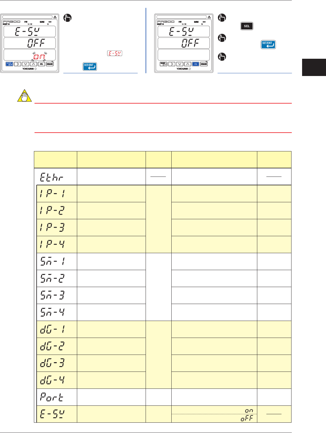
Parameter Setting Types and Ranges
Ethernet communication menu
IP address-1
IP address-2
IP address-3
IP address-4
Subnet mask-1
Subnet mask-2
Subnet mask-3
Subnet mask-4
Default gateway-1
Default gateway-2
Default gateway-3
Default gateway-4
Port number
Ethernet setting switch
Integral
numeric
value
Integral
numeric
value
Integral
numeric
value
Integral
numeric
value
Selection
0 to 255
0 to 255
0 to 255
0 to 255
0 to 255
0 to 255
0 to 255
0 to 255
0 to 255
0 to 255
0 to 255
0 to 255
502, 1024 to 65535
ON
OFF
Menu to shift to the parameters of
Ethernet communication
192
168
1
255
255
255
0
0
0
0
0
502
1
Parameter Symbol Parameter Name
Setting
Type
Setting Range (Details)
Initial Value
(Factory-set
Value)