
Energy Meter Manual
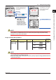
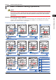
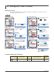
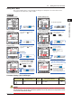
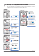
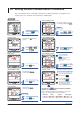
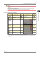
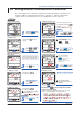
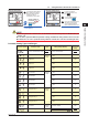
Table Of Contents
- Introduction
- Notices
- Checking the Package
- Checking the Model and Suffix Codes
- Contents
- Chapter 1 Installation and Wiring
- 1.1 Installation with the ANSI 4-inch Round Form or JIS 110-square Instrument Size
- 1.2 Installation with the DIN 96-square Instrument Size
- 1.3 Wiring
- Crimping Terminal Recommendations
- Single-phase two-wire system (voltage input, current input, power supply)
- Single-phase three-wire system (voltage input, current input, power supply)
- Three-phase three-wire system (voltage input, current input, power supply)
- Three-phase four-wire system (voltage input, current input, power supply)
- Three-phase four-wire system (2.5 element) (voltage input, current input, power supply)
- Other Wiring
- 1.4 Attaching the Dust Cover and Terminal Cover
- Chapter 2 Preparations before Starting Measurement (Set up the PR300 First)
- Chapter 3 Parameter Setting Operations
- 3.1 Basic Parameter Setting Operations
- 3.2 Setting the VT and CT Ratios
- 3.3 Setting the Integrated Low-cut Power
- 3.4 Setting RS-485 Communication Conditions
- 3.5 Setting Ethernet Communication Conditions
- 3.6 Setting Pulse Output Conditions
- 3.7 Setting Analog Output Conditions
- 3.8 Setting Demand Measurement Conditions
- 3.9 Setting the Measured Value Display Pattern
- 3.10 Setting the “Indicator-out” Mode and Locking Parameters
- Chapter 4 Operation for Display of Measurement Items and Measurement Method
- 4.1 Measurement Items
- 4.2 Switching Display Pattern
- 4.3 Displaying Measured, Instantaneous, and Maximum/Minimum Values
- Example Display and Measuring Ranges of Active Power (Regenerative Power)
- Example Display and Measuring Ranges of Reactive Power
- Example Display and Measuring Ranges of Apparent Power
- Example Display and Measuring Ranges of Voltage
- Example Display and Measuring Ranges of Current
- Example Display and Measuring Ranges of Power Factor
- Example Display and Measuring Ranges of Frequency
- How to Switch between Instantaneous Value, Maximum Value, and Minimum Value
- 4.4 Phase Switching for Voltage and Current
- 4.5 Displaying Energy Values
- 4.6 Resetting Measured Values
- 4.7 Demand Measurement (Optional Measuring Function)
- Chapter 5 Troubleshooting
- Appendix
- Appendix 1 Specifications of PR300
- Measuring Function
- Power Items and Equations
- Input Specifications
- Digital Input Specifications
- Analog Output Specifications (additional output function)
- Pulse Output Specifications (additional output function)
- Demand Alarm Output Specifications (optional measuring function)
- Communication Specifications
- Standard Performance
- Safety and EMC Standards
- Environmental Conditions
- Mounting and Shape
- Appendix 2 System Reset
- Appendix 3 Parameter Map
- Appendix 4 Parameter List
- Appendix 5 Alphanumeric Characters Table for 7-segment LED
- Appendix 1 Specifications of PR300
- Index
- A
- C
- D
- E
- H
- I
- M
- O
- P
- R
- S
- T
- V
- W
- Wiring diagram
- Single-phase two-wire system
- Single-phase three-wire system
- Three-phase three-wire system
- Three-phase four-wire system
- Three-phase four-wire system (2.5 element)
- Analog output
- Demand alarm output
- Demand alarm release
- Ethernet communication
- Integration control signal
- Palse output
- RS-485 communication
- Wiring diagram
Parameter Setting Operations
3-1
IM 77C01E01-01E
1
2
3
4
5
A
I
Chapter 3 Parameter Setting Operations
3.1 Basic Parameter Setting Operations
NOTE
Set parameters only after setting the phase and wire system and the voltage range. If you change the
phase and wire system or voltage range after setting a parameter, the parameter will be initialized (to
a factory-set value). Parameters related to RS-485 and Ethernet communications will not be initial-
ized, however.
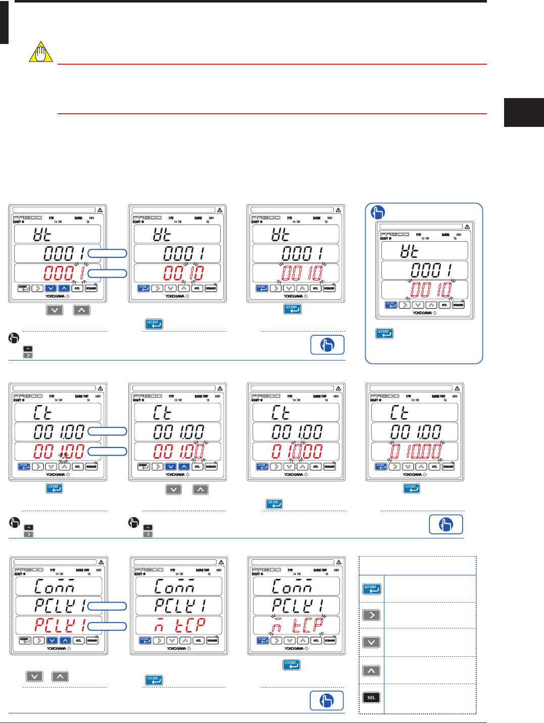
Methods of Changing Parameter Setpoints
Four setting types - integral numeric value, fixed-point numeric value, floating-point numeric value, and
selection - have been defined for the parameters of the PR300. For each setting type, the following
explains basic operations used to set parameters.
Integral numeric value or fixed-point numeric value
Using or ,
change the numeric
value.
To move to the digit to be
changed, use the following keys:
To the left
To the right
After changing the
numeric value, press
once.
Press while all
digits of the setpoint are
blinking.
Press any key other than
while all digits of the
setpoint are blinking. The
PR300 returns to the screen
in step
1
.
To re-set the parameter:
123
This confirms
the setpoint.
This causes all digits of the
setpoint to start blinking.
Current value
Setpoint
Floating-point numeric value
Using or ,
change the numeric
value.
After changing the
numeric value, press
once.
Press while all
digits of the setpoint are
blinking.
234
This confirms
the setpoint.
This causes all digits of the
setpoint to start blinking.
Using , confirm the
number of decimal
places.
1
Current value
Setpoint
To move to the digit to be
changed, use the following keys:
To the left
To the right
To move the decimal point, use
the following keys:
To the left
To the right
Selection
Key operations used
to set parameters
Moves from the Measured Value
screen to the Parameter screen
(hold down the key), or confirms
the setpoint.
Shows a parameter from the menu,
moves through the digits of a setpoint
(numeric value) to the right, or moves
the decimal point to the right.
Shows the next parameter or
menu item, or changes the
setpoint.
Shows the previous parameter or
menu item, or changes the
setpoint.
Returns from the Parameter screen
to the Menu screen, moves through
the digits of a setpoint (numeric
value) to the left, or moves the
decimal point to the left.
Change the setpoint using
or
.
After changing the
setpoint, press
once.
Press while all
digits of the setpoint are
blinking.
123
This confirms
the setpoint.
This causes all digits of the
setpoint to start blinking.
Current value
Setpoint