
User guide


4-11
IM MW180-01E
Calibrator
1
2
3
4
5
App
Index
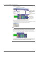
• 6-Channel, Medium-Speed, Four-Wire RTD Resistance Input Module (MX110-V4R-M06)
Measurement Range to Be Calibrated Input Value 1 Input Value 2
20 mV 0 mV on Ch1 20 mV on Ch2
60 mV 0 mV on Ch1 60 mV on Ch2
200 mV 0 mV on Ch1 200 mV on Ch2
1 V 0 V on Ch1 1 V on Ch2
2 V 0 V on Ch1 2 V on Ch2
6 V 0 V on Ch1 6 V on Ch2
20 V 0 V on Ch1 20 V on Ch2
100 V 0 V on Ch1 100 V on Ch2
RTD(1 mA)20 mV 0 Ω on Ch3 20 Ω on Ch4
RTD(1 mA)60 mV 0 Ω on Ch3 60 Ω on Ch5
RTD(1 mA)200 mV 0 Ω on Ch3 200 Ω on Ch6
RTD(1 mA)600 mV 0 Ω on Ch3 300 Ω on Ch4
RTD(0.25 mA)600 mV 0 Ω on Ch3 2400 Ω on Ch5
RTD(0.25 mA)1 V 0 Ω on Ch3 3000 Ω on Ch6
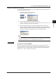
• 4-CH, Medium-Speed Strain Input Module (MX112-B12-M04, MX112-B35-M04,
MX112-NDI-M04)
Measurement Range to Be Calibrated Connection Value 1 Connection Value 2
2000 µSTR (strain) 120.000 Ω on Ch2 117.154 Ω on Ch2
20000 µSTR (strain) 120.000 Ω on Ch2 113.010 Ω on Ch2
200000 µSTR (strain) 120.000 Ω on Ch2 80.000 Ω on Ch2
Use a 4-gauge method connection when performing calibration. For information on
this connection, see section 2.4 of the MW100 Data Acquisition Unit User’s Manual (IM
MW100-01E).
•
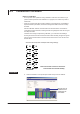
8-CH, Medium-Speed Analog Output Module (MX120-V
AO-M08)
Adjust so that all channels output 0 V and 10 V. This differs from other input modules.
Range to Be Calibrated Output Value 1 Output Value 2
10 V 0 V 10 V
Note
• For a description of the measurement range and accuracy of each input module, see
chapter 5 in the MW100 Data Acquisition Unit User’s Manual (IM MW100-01E).
• For procedures and wiring for calibration, see the MW100 Data Acquisition Unit User’s
Manual (IM MW100-01E), section 4.4.
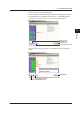
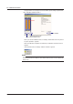
4.2 Calibration Procedure