User’s Manual Model EXAxt AV550G HART Protocol IM 11M12D01-51E R IM 11M12D01-51E 2nd Edition
i INTRODUCTION This is the HART Communicator manual for the EXAxt series of Model AV550G. This manual is described under the HART equipment that is ready to operate. When using the HART Protocol for the EXAxt AV550G, please refer to the following instruction manuals. n Special descriptions in this manual This manual describes the products and instruction manuals listed below.
ii After-sales Warranty Do not modify the product. During the warranty period, for repair under warranty carry or send the local sales representative or service office. Yokogawa will replace or repair anyproduct to the damaged parts and return the product to you. Before returning a product for repair under warranty, provide us with the model name and serial number and a description of the problem. Any diagrams or data explaining the problem would also be appreciated.
i Model EXAxt AV550G HART Protocol IM 11M12D01-51E 2nd Edition CONTENTS INTRODUCTION........................................................................................................i u After-sales Warranty . .........................................................................................ii 1. Operation via HART Communicator....................................................... 1-1 1.1 2. 3. 1.1.1 Interconnection between AV550G and HART Communicator........... 1-1 1.1.
ii IM 11M12D01-51E
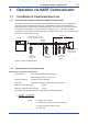
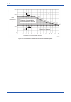
1-1 <1. OPERATION VIA HART COMMUNICATOR> 1. Operation via HART Communicator 1.1 Conditions of Communication Line 1.1.1 Interconnection between AV550G and HART Communicator The HART Communicator can interface with the AV550G from the control room, the AV550G site, or any other wiring termination point in the loop, provided there is a minimum load resistance of 250Ω between the connection and the receiving instrument.
1-2 <1. OPERATION VIA HART COMMUNICATOR> 800 Outside of range 600 Load Resistance (Ω) Range of acceptable load resistance values 400 200 Outside of range 0 1 2 3 4 5 6 7 8 9 10 11 12 13 14 15 Number of connected field devices F010201.ai Figure 1.
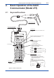
2-1 <2. Basic Operation of the HART Communicator (Model 275)> 2. Basic Operation of the HART Communicator (Model 275) 2.1 Keys and Functions Communication Cable LCD (Liquid crystal display) (21 charactersx8 lines) Function keys Functions of the keys are indicated on the display. Move the inverse video bar (cursor) on the display to select the desired item. Hot Key Call up Hot Key Menu as follows: 1. Ave-a O2 display 2. Ch O2 display 3. Chng Wrt Protect Power ON/OFF 1.
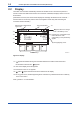
2-2 <2. Basic Operation of the HART Communicator (Model 275)> 2.2 Display The HART Communicator automatically searches for AV550G on the 4 to 20 mA loop when it is turned on. When the HART Communicator is connected to a AV550G, it displays “Online” menu as shown below. (If AV550G is not found, the communicator displays the message “No Device Found. Press OK....” Press the OK ‘F4’ function key and the main menu appears. Please retry after confirming the connection with the AV550G.
2-3 <2.
2-4 <2. Basic Operation of the HART Communicator (Model 275)> AV550G: Tag Process variables Diag / Service Basic setup Detailed setup Review Device setup PV PV URV PV LRV 1 Tag PV Unit Xfer fnctn ESC ENTER Operation Display 1 at left appears when the S HART communicator is turned on. or STU T 1 U Select " Device set up" . 1 AV550G: Online Device setup PV PV URV PV LRV DEL F020301.ai Display 1 2 3 4 HELP 21.
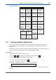
2.4 <2. Basic Operation of the HART Communicator (Model 275)> 2-5 Entering, Setting and Sending Data The data, which are entered with the keys, are set in the HART Communicator by pressing ENTER (F4). Then, by pressing SEND (F2), the data are sent to the AV550G. Note that the data are not set in the AV550G if SEND (F2) is not pressed. All the data set with the HART Communicator are held in memory unless power is turned off, so all data can be sent to the AV550G in one burst.
2-6 1 <2. Basic Operation of the HART Communicator (Model 275)> AV550G: Tag Display Operation F4 FIC-1A HELP (ENTER) DEL ESC ENTER 2 AV550G: Basic setup 1 Tag FIC-1A 2 PV Unit 3 Xfer fnctn Linear HELP SEND F2 % 1 Tag FIC-1A 2 PV Unit 3 Xfer fnctn Linear SAVE (SEND) Press SEND (F2) to send the data to the AV550G. is flashing during communication. HOME 3 AV550G:FIC-1A Basic setup HELP Press ENTER (F4) to set the data in the HART Communicator after entering the data.
<3. Parameters> 3. Parameters 3.
3-2 <3.
3-3 <3. Parameters> Online Menu 1 Device setup 2 PV 3 Basic setup 1 Tag 3 PV URV 2 PV Unit 4 PV LRV 3 Xfer fnctn 4 Detailed setup 1 Control 1 Error Ctrl card 2 Alarm Ave-a oxygen Ave-b oxygen Ave-c oxygen Process gas Cal gas press lo Inside temp continued continued on the next page. on the next page. T3003.
3-4 <3. Parameters> Online Menu 1 Device setup 2 PV 4 Detailed setup 2 Channels 1 Ch1 detailed setup 3 PV URV 2 Ch2 detailed setup (ditto) 4 PV LRV 3 Ch3 detailed setup (ditto) 4 Ch4 detailed setup (ditto) 5 Ch5 detailed setup (ditto) 6 Ch6 detailed setup (ditto) 7 Ch7 detailed setup (ditto) continued continued on the next page. on the next page.
3-5 <3. Parameters> Online Menu 1 Device setup 2 PV 4 Detailed setup 3 Channel status 1 Ch1 sts 3 PV URV 2 Ch2 sts 4 PV LRV 3 Ch3 sts 4 Ch4 sts 5 Ch5 sts 6 Ch6 sts 7 Ch7 sts 8 Ch8 sts continued on the next page.
3-6 <3. Parameters> Online Menu 1 Model 1 Device setup 5 Review 2 PV 2 Distributor 3 PV URV 3 PV Snsr unit 4 PV LRV 4 PV USL 5 PV LSL 6 PV Min span 7 PV % rnge 8 Xfer fnctn 9 PV Rnge unit PV URV PV LRV PV AO PV AO Alrm type Snsr s/n Write protect Manufacturer Dev id Tag Descriptor Message Date Universal rev Fld dev rev Software rev Burst mode Burst option Poll addr T3006.
3.2 3.2.1 3-7 <3. Parameters> Setting Parameters Burst Mode The AV550G continuously sends the data stored in it when burst mode is set “On”. Either one of measured value, % output value, or 4 to 20 mA output value can be selected and sent. The data is sent periodically at 75 ms intervals as a digital signal when the AV550G is set in burst mode. Therefore, communication by the HART simultaneous communicator is also possible. Setting of Burst Mode Call up “Burst option” display. 1.Device setup ---> 4.
3-8 3.2.2 <3. Parameters> Multidrop Mode Field devices in multidrop mode refer to the connection of several field devices on a single communication line. Up to 15 field devices can be connected when set in multidrop mode. To activate multidrop communication, each field device address must be changed to a unique number in the range 1 to 15. This change deactivates the 4 to 20mA output and changes it to 4mA. Setting of Multidrop Mode Call up “Poll addr” display. 1.Device setup ---> 4.Detailed setup ---> 4.
3-9 <3. Parameters> 4 HART Communicator Utility 1 2 3 4 5 Select " Configure Communication. " Configure Communic System Information Listen for PC Storage Location Simulation 5 HART Communicator Configure Communica Select " Polling " . 1 Polling 2 Contrast 3 Off Time 4 Ignore diagnostics 5 Delete Configs HELP 6 HART Communicator Polling Ask Before Polling Never Poll Ask Before Polling Always poll Digital poll HELP ESC ENTER F4 x3 Select " Digital Poll " and press ENTER (F4).
3-10 <3. Parameters> Releasing from Multidrop Mode First, call up the “Poll addr” display, and set the address to 0. Second, call up the “Polling” display, and set “Never Poll”. If the above releasing method is carried out in the reverse order “Online Menu” can not be called up. NOTE 3.2.3 Software Write Protect AV550G configured data is saved by the write protect function.
<3. Parameters> 5 AV550G: Chng Wrt Protect 1 2 3 4 Write protect Enable wrt 10min New password Software seal Keep 3-11 Yes SAVE F030216-1.
3-12 <3. Parameters> Changing Password Example: To change the password from 1234 to 6789A Call up “Chng Wrt Protect” display. Hot key ---> 3.Chng Wrt Protect 1 Display AV550G: Chng wrt Protect 1 Write protect 2 Enable wrt 10min 3 New password 4 Software seal Keep Operation No Select the " Enable wrt 10min" . VWX 2 SAVE 2 AV550G: Enter current password to enable to write for 10 minutes: 1234 DEL “1 2 3 4” ' Set the old password " 1234 " and press ENTER (F4).
3-13 <3. Parameters> 8 AV550G: It changed the state of protection related password. F4 (OK) OK NOTE Press OK (F4). F030219-1.ai 1. Enable wrt 10 min releases write protect status for 10 minutes. While write protect status is released, enter a new password in the New Password field. It will not be possible to set a new password when 10 minutes have elapsed. 2.
3-14 <3. Parameters> 3.3 Calibration Here we explain how to excute Semi-Auto Calibration using HART communications. This requires the AV550G Calibration mode to have been set to Semi-Auto or Auto. For further details, refer to “Section 9. Calibration” in the AV550G Instruction Manual. NOTE Calibration-related parameters can not be set remotely using HART communication. Calibration can not be canceled using HART communication. Call up “Calibration” display. 1. Device setup ---> 2.
3.4 3-15 <3. Parameters> Indication Check Here we explain how to excute a Semi-Auto Indication check using HART communications. This requires the AV550G Indication check mode to have been set to Semi-Auto or Auto. For further details, refer to “Section 10. Indication Check” in the AV550G Instruction Manual. NOTE Indication-Check-related parameters can not be set remotely using HART communication. Indication Check can not be canceled using HART communication.
3-16 <3. Parameters> 3.5 Blow Back Here we explain how to excute a Semi-Auto Blow Back using HART communications. This requires the AV550G Blow back mode to have been set to Semi-Auto or Auto. For further details, refer to “Section 10.5 Blow Back” in the AV550G Instruction Manual. NOTE Blow-Back-related parameters can not be set remotely using HART communication. Blow Back can not be canceled using HART communication. Call up “Blow back” display. 1. Device setup ---> 2.
3.6 3-17 <3. Parameters> Self-Diagnostics Here we explain how to check Error or Alarm messages from the AV550G using a HART Communicator. The table below shows the correspondence between error and alarm messages displayed on the HART Communicator and corresponding error and alarm messages in the AV550G. For more details about these error and alarm messages, and troubleshooting procedures, refer to “Section 12. Troubleshooting” in the AV550G Instruction Manual. 3.6.
3-18 <3. Parameters> 3.6.2 Channel Card Self-Diagnostics Call up “Detailed setup” display. 1. Device setup ---> 4.
<3. Parameters> 3-19 Channel card Control card Table3.1 AV550G Alarms and Errors displayed on HART Communicator HART Communicator Display Ctrl card Ave-a oxygen Ave-b oxygen Ave-c oxygen Process gas Cal gas press lo Inside temp Cell voltage Heater temp Ch card Card comm. Oxygen Zero conc. ratio Span conc.
3-20 <3. Parameters> 3.7 Status Check You can check Channel Card Status using the HART Communicator. The meanings of these status indications are displayed in the table below. Call up “Detailed setup” display. 1. Device setup ---> 4.
4-1 <4. Maintenance> 4. Maintenance Various sensor data can be viewed on the HART Communicator. For more details, refer to “Section 10.1 Display” in the AV550G Instruction Manual. Call up “Channels” display. 1. Device setup ---> 4. Detailed setup ---> 2.
4-2 IM 11M12D01-51E <4.
i Revision Information Title : Model EXAxt AV550G HART Protocol Manual No. : IM 11M12D01-51E Feb. 2005/1st Edition Newly published Dec 2010/2nd Edition Revised and Corrected over all n If you want more information about Yokogawa products, you can visit Yokogawa’s home page at the following web site. Home page: http://www.yokogawa.com/ n Written by Environmental & Analytical Products PMK Group IA Div.
Blank Page