
Manual

IM 11M12D01-01E
5-10
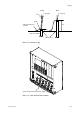
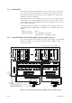
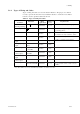
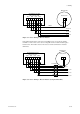
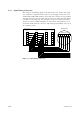
5.2.5 Signal Wiring to Detectors
This wiring is for transmitting signals of cell electromotive force, thermocouple output
and cold junction compensation from a detector to the averaging converter. Use 6-core
shielded PVC insulated PVC sheathed control cables. The conductor two-way resistance
should be 10 Ω or less. Keep the cables away from the power wiring. If a cable gland is
not installed on the wiring hole of the averaging converter, use a wire with an outside
diameter of 17 mm or smaller. If installed, use a wire with an outside diameter of 6 to
12 mm. The shields should be connected to cable shield ground terminals on the case of
the averaging converter.
1 1 1 1
2 2 2 2 1 2 3 4 5 6
3 3 3 3
4 4 4 4
5 5 5 5
6
6 6 6
To Detecter #2
ZR22G / ZO21D
CH1
CH2
Detector #1
CH3
CH4
Shield
Averaging Converter
Channel Card
CELL
TC
CJ
1
2
1
2
1
2
Figure 5.9 Signal Wiring to Detectors