
Manual


IM 11M12D01-01E
2-23
2. Specifications
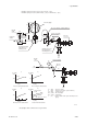
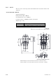
38
Approx.88
40
20
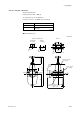
Qa
L
200
100
0
5
10
15
P= 0.5
0
40
30
40
60
80
Po (kPa)
Qa (l/min)
0
-1.0
-0.5
40
60
80
Pg (kPa)
0
8
4
40
60
80
Qg (l/min)
L (m)
P (kPa)
P (kPa)
P (kPa)
Po (kPa) : Pressure setting
P (kPa) : Drive pressure (at the ejector entrance)
Pg (kPa) : Suction pressure
Qa (l/min) : Air consumption
Qg (l/min) : Suction flow
L (m) : Distance between the ejector and the pressure
gauge
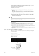
Needle
valve
Pressure gauge
39
lnstrument
air inlet
f43
Height when
fully open
Approx.67
Not included in high
temperature use
auxiliary ejector.
f63f4 or 1/4 inch, conduit (stainless)
Ejector assembly
PT 1/2 male
Approx.
70
Auxiliary ejector for
high-temperature
mounting place use.
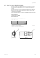
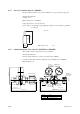
Detector
Needle
valve
Pressure gauge
Ejector
Po
Air
source
Gas
Pg
Qg
Gas pressure : -15 Pa
Air consumption characteristicsPressure setting characteristics
Suction pressure characteristics
Suction flow characteristics
F2.9E.EPS
Gas Pressure:
0 kPa
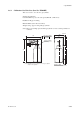
1)
2)
3)
4)
E7046EC ; Piping connections, Rc1/4( p part) or Rc1/4( pp part ),
E7046EN ; Piping connections,1/4NPT female ( p part) or 1/4NTP male( pp part )
p
p
p
pp
(Note) Pipes and connectors are not provided.