
Manual

IM 11M12D01-01E
8-13
8. Detailed Data Setting
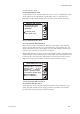
8.3 Assigning Contact Outputs
The averaging converter provides the following outputs:
1) "Function" contact outputs (DO1~DO4): Function can be allocated by user.
2) Common (representative) error contact (DO5): Represents an error in any channel.
3) Individual channel error contacts (DO-CH1~DO-CH8): Individual channel error
outputs, one per channel.
For details of errors, refer to Sec. 12.1 Displays and Remedies When Errors Occur.
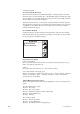
Each contact output is Form C (transfer contact) with three terminals: COM / NC / NO
(COM=common, NC=Normally Closed, NO=Normally Open) using a mechanical relay
with non-wetted contacts. Ensure that contact rating is not exceeded.
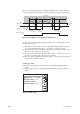
The four function-specific contact outputs can be programmed to be normally operated
(NC or NO selectable). For safety the error contacts are factory fixed to be normally
closed. How to assign conditions to function contact outputs is described below. Table
8.4 shows the conditions that can be assigned to function-specific contacts.
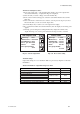
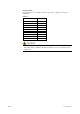
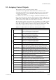
Table 8.4 Conditions that can be allocated to function-specific contacts
T8.4E.eps
High High Alarm ON then High High alarm results in contact output.
However, High High alarm must be ON (enabled).
Refer to Sec. 8.2 Oxygen Concentration Alarms.
High Alarm If ON then High alarm results in contact output.
However, High alarm must be ON (enabled).
Refer to Sec. 8.2 Oxygen Concentration Alarms.
Low Alarm If ON then Low alarm results in contact output.
However, Low alarm must be ON (enabled).
Refer to Sec. 8.2 Oxygen Concentration Alarms.
Low Low Alarm If ON then Low Low alarm results in contact output.
However, Low Low alarm must be ON (enabled).
Refer to Sec. 8.2 Oxygen Concentration Alarms.
CAL coefficient alarm If ON then calibration-time Zero coefficient error, Span coefficient error,
or an electrode potential stability error results in contact output.
CAL gas pressure lowIf ON then a contact input indicating calibration gas pressure low results
in contact output. This is a calibration gas pressure low answerback signal.
Corresponding contact input must be allocated to calibration gas pressure low.
Process gas alarm If ON then a contact input indicating process gas pressure alarm results
in contact output. This is a process gas pressure alarm answerback signal.
Corresponding contact input must be allocated to process gas pressure alarm.
Temperature alarm If ON then if internal temperature of averaging converter is over limit,
contact output occurs. When the converter is used under severe environmental
temperature conditions, you can use this contact to switch on a cooler
Error If ON then any type of error causes contact output.
Acts the same as common error contact.
Warmup If ON then during warmup there is contact output.
For definition of warmup, see Sec. 8.1.2 Setting Output Hold.
Output range switching If ON then while contact-input range-switching signal is detected,then there is
contact output. This is a range-switching input answerback signal.
Corresponding contact input must be allocated to measurement range switching.
Maintenance If ON then while (under) maintenance there is contact output.
For definition of (under) maintenance, see Sec. 8.1.2 Setting Output Hold.
Calibration If ON then while (under) calibration there is contact output.
For definition of (under) calibration, see Sec. 8.1.2 Setting Output Hold.
Indication check If ON then during indication check there is contact output.
For definition of indication check, see Sec. 10.4 Indication Check.
Blowback If ON then there is Blowback switch contact output.
For definition of blowback, see Sec. 10.5 Blowback.
3rd Check Gas If ON then during indication check, there is contact output
to operate 3rd Check Gas solenoid valve.
For definition of indication check, see Sec. 10.4 Indication Check.
Item Condition for contact output
Alarms
Other statuses