
Manual

IM 11M12D01-01E
6-6
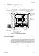
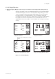
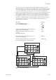
6.2.2.3 Display Configuration
Display configuration is shown below.
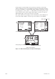
25%O2
0%O2
Hold
Tag:
Ch1
21.0
%
O
2
Ave-a 21.0 %O2
Ave-b 21.0 %O2
Ave-c 21.0 %O2
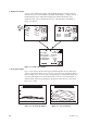
Tag:
Ch1
21.0%
Ch2
21.0%
Ch3
21.0%
Ch4
21.0%
Ch5
21.0%
Ch6
21.0%
Ch7
21.0%
Ch8
20.7%
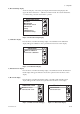
Enter
other
Entry your password
A
B C
D
E F
G
H I
J
K L
M
N O
P
Q R
S
T U
V
W X
Y
Z @
0-9
Space
- S
Enter
other
Entry your password
A
B C
D
E F
G
H I
J
K L
M
N O
P
Q R
S
T U
V
W X
Y
Z @
0-9
Space
- S
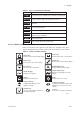
+ Channel Indication Area
r Calibration
r Indication check
r Blow back
r Maintenance
r Commissioning
Password entry display will appear
only if the desired operation is
protected by password. Password
protection is factory set to
disabled.
Password Entry for Maintenance
Password Entry for Commissioning
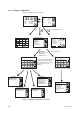
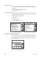
Enter
Execution/Setup
Calibration
r Indication check
r Blow back
Setup
r Maintenance
r Commissioning
F06E.EPS
Execution
F03-cE.EPS
Ch1
Cell voltage:
0 . 9 mV
Thermo voltage:
2 9 . 4 mV
C.J.resistance: 1 1 7 0 . 2 V
Cell temperature: 7 5 0 8C
C.J.temperature: 4 3 8C
Warmup
Hold
Enter
Commissioning
Basic setup
F11E.EPS
r mA-output setup
r Alarm setup
r Contact setup
r Average group setup
r Others
Enter
Maintenance
Display setup
F10E.EPS
r Calibration setup
r Indication check setup
r Blow back setup
r mA-output loop check
r Contact check
r Channel card power
Enter
Start blow back
r Cancel blow back
F09E.EPS
Blow back
Enter
Manual ind. check
r Semi-auto ind. check
F08E.EPS
Indication check
Enter
Manual calibration
r Semi-auto calibration
F07E.EPS
Calibration
Figure 6.5 Display Configuration of AV550G