
Instruction Manual


<3. ABOUT FIELDBUS>
3-1
IM 11M12D01-61E
3. ABOUT FIELDBUS
3.1 Fieldbus Overview
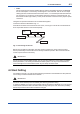
The Fieldbus digital communications protocol supports the requirements of large-scale process
control systems that have numerous eld devices,and is regarded as a worthy successor to the
conventional 4-20mA analog loop.
The AV550G Fieldbus functions are designed to satisfy the Foundation Fieldbus standard in order to
ensure compatibility with other makers’ Fieldbus products.
The Fieldbus implementation for the AV550G supports three AI, two DI, MAI and MAO blocks.
For an overview of Fieldbus engineering, design, installation, startup and maintenance, refer to
Foundation Fieldbus TI 38K03A01-01E.
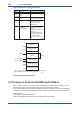
3.2 Fieldbus Representation of AV550G
The Fieldbus Representation of the AV550G is two Virtual Field Devices (VFD) as follows:
3.2.1 System/Network Management VFD
• Sets node addresses and Physical Device tags (PD Tag) necessary for communication.
• Controls the execution of function blocks.
• Manages operation parameters and communication resources (Virtual Communication
Relationship: VCR).
3.2.2 Function Block VFD
(1) Resource (RS) block
• Manages the status of AV550G hardware.
• Automatically informs the host of any detected faults or other problems.
(2) Transducer (TR) block
• This conditions each oxygen concentration sensor output signal and connects it to an AI function
block.
It also transmits abnormality and alarm signals to DI function blocks.
(3) AI function blocks (three)
• There are three AI blocks (AI1 thru’ AI3) which can condition (perform scaling and rst-order-lag
damping for) three sensor signals.
AI1 is averaging-value “a” output signal block.
AI2 is averaging-value “b” output signal block.
AI3 is averaging-value “c” output signal block.
* Simulation functions support scaling and rst-order-lag damping.
(4) DI function blocks (two)
DI1 is an alarm output switch, and
DI2 is an abnormality output switch.