User’s Manual Model EXAxt AV550G Fieldbus Communication Type IM 11M12D01-61E R IM 11M12D01-61E 2nd Edition
i Model EXAxt AV550G Fieldbus Communication Type IM 11M12D01-61E 2nd Edition CONTENTS 1. INTRODUCTION......................................................................................... 1-1 n Regarding This Manual................................................................................................ 1-1 n Warranty........................................................................................................................ 1-1 n Safe Use of This Product................
ii 6. 5.6.3 View Objects..................................................................................... 5-10 5.6.4 AI Function Block Parameters.......................................................... 5-19 5.6.5 Transducer Block Parameters.......................................................... 5-19 5.6.6 DI Function Block Parameters.......................................................... 5-20 5.6.7 MAI Function Block Parameters..............................................
iii A4.4 MAO Function Block....................................................................................... A-23 APPENDIX 5. LINK MASTER FUNCTIONS......................................................A-24 A5.1 Link Active Scheduler.................................................................................... A-24 A5.2 Link Master...................................................................................................... A-24 A5.3 Transfer of LAS....................
iv APPENDIX 7. DD MENU STRUCTURE.................................................A-42 Revision Information ...............................................................................................
1-1 <1. INTRODUCTION> INTRODUCTION This manual covers only items that are specific to the FOUNDATION Fieldbus type of the AV550G Averaging Converter and that are not contained in the User’s Manual of the AV550G. For details of the operation and performance of the AV550G, refer to IM 11M12D01-01E. n Regarding This Manual • This manual should be passed on to the end user. • The contents of this manual are subject to change without prior notice. • All rights reserved.
1-2 <1. INTRODUCTION> - Use of the product in question in a location not conforming to the standards specified by Yokogawa, or due to improper maintenance of the installation location. - Failure or damage due to modification or repair by any party except Yokogawa or an approved representative of Yokogawa. - Malfunction or damage from improper relocation of the product in question after delivery.
1-3 <1. INTRODUCTION> • The following safety symbol marks are used in this Manual: WARNING Indicates a potentially hazardous situation which, if not avoided, could result in death or serious injury. CAUTION Indicates a potentially hazardous situation which, if not avoided, may result in minor or moderate injury. It may also be used to alert against unsafe practices. IMPORTANT Indicates that operating the hardware or software in this manner may damage it or lead to system failure.
1-4 <1. INTRODUCTION> • Failure caused by any usage out of scope of recommended usage. • Any damage from fire, earthquake, storms and floods, lightning, disturbances, riots, warfare, radiation and other natural changes. Yokogawa does not warrant conformance with the specific application at the user site. Yokogawa will not bear direct/indirect responsibility for damage due to a specific application.
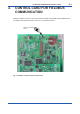
2. <2. FIELDBUS COMMUNICATION CONTROL CARD> 2-1 CONTROL CARD FOR FIELDBUS COMMUNICATION Fieldbus simulation functions on the control card are enabled using the SIMULATE_ENABLE switch. For details of the simulation functions, see Sec. 6.3 Simulation Functions. SIMULATE_ENABLE 1 Switch 2 Fig. 2.1 Fieldbus Communications Control Card.
Blank Page
3-1 <3. ABOUT FIELDBUS> 3. ABOUT FIELDBUS 3.1 Fieldbus Overview The Fieldbus digital communications protocol supports the requirements of large-scale process control systems that have numerous field devices,and is regarded as a worthy successor to the conventional 4-20mA analog loop. The AV550G Fieldbus functions are designed to satisfy the Foundation Fieldbus standard in order to ensure compatibility with other makers’ Fieldbus products.
3-2 <3. ABOUT FIELDBUS> (5) MAI function block • Each of these corresponds to the oxygen concentration signal output. (6) MAO function block • 3.3 This block can acquire field data; a total of up to eight signals.
4-1 <4. GETTING STARTED> 4. GETTING STARTED Fieldbus is a wholly digital communications protocol, and so differs from the conventional 4 to 20 mA analog loop. It is recommended that new users try the Fieldbus familiarization exercises described in this section. It is expected that these can be done in a laboratory or the like. 4.1 Connection of Devices The following equipment is required for a Fieldbus laboratory setup: • Power supply: Fieldbus requires a special power supply.
4-2 <4. GETTING STARTED> Shield Conductors Approx. 40 cm Fig-1.ai Run the cable through the wiring hole on the AV550G. Fix the cable with a cable gland, if necessary. Open the common mode filter supplied, and wind one turn of the two conductors on it. The cable length between the common mode filter and the wiring hole should not exceed 5 cm. Close the common mode filter, taking care not to catch the cable in it, and then lock it.
<4. GETTING STARTED> • 4-3 Cable: This is used to interconnect the Fieldbus devices. Refer to the Fieldbus Overview TI 38K03A0101E for a description. In a test setup, a total length of 2-3m is sufficient, and we can use simple cabling (wire with crosssectional area of at least 0.9mm2 , run as twisted pair with twist interval of not more than 5 cm (2 inches)). The termination will need to match the connected devices. For the AV550G use wire lugs for M3.5 (3.5 mm) screw terminals.
4-4 <4. GETTING STARTED> Table 4.2 Parameters required for operation Symbol Parameter name Description and Value V (ST) Slot-Time Set a value of 4 or greater V (MID) Minimum-Inter-PDUDelay Set a value of 4 or greater V (MRD) Maximum-ReplyDelay Set this such that V(MRD) x V(ST) is 12 or greater. V (FUN) First-Unpolled-Node Defines the first address that can be used by host. Set a value of 15 or greater (hex).
4-5 <4. GETTING STARTED> [ See explanation of numbers in Sec. 4.4 below. The xxxxxxxx is like a serial no. that is unique to each unit manufactured. ] If the AV550G is not detected on the Fieldbus, check its address setting and also check the available free addresses on the Fieldbus. Unless the PD tag and node address are specified at order time, then the factory defaults above will apply.
4-6 <4. GETTING STARTED> 4.7 Generating Alarms If the host is able to receive alarms, then enable alarm capture on the host and generate an alarm from the AV550G to test this. At the time of shipping from the factory, virtual communication relationship VCR-7 of AV550G is set up for this purpose. Default setting is for all alarms to be disabled. Try enabling one alarm as follows: Set the value of link object 3 (index 30002) to (0, 299, 0, 6, 0). Refer to Sec. 5.6.1 Link Objects.
5-1 <5. CONFIGURATION> 5. CONFIGURATION This section describes how to customize the functions and tailor the performance of the AV550G to suit specific applications. Because multiple devices are connected to the Fieldbus, it is important to take care to consider the network as a whole to eliminate any design defects that might adversely affect the network as a whole.
5-2 <5. CONFIGURATION> • Fieldbus Cable: Cable is used for interconnecting Fieldbus devices. Refer to Fieldbus Technical Information TI 38K3A01-01E for details. You need enough cable to interconnect all Fieldbus devices. You can use terminal boards or terminal boxes for running side “spurs” off the “main trunk”, however you should ensure that the length of such “spur” runs is as short as possible.
5-3 <5. CONFIGURATION> 0x00 Unused 0x0F 0x10 Bridge device 0x13 0x14 LM devices V(FUN) Unused V(FUN)+V(NUN) V(NUN) Basic devices 0xF7 0xF8 Default addresses 0xFB 0xFC 0xFF Portable device addresses F0501.ai Figure 5.1 Available Range of Node Addresses For all Link Master (LM) devices, the parameters listed in Table 5.2 are set to ensure stable operation.
5-4 <5. CONFIGURATION> 5.3 Function Block Link Definitions The output of one function block may be linked to the input of another. For the AV550G, the three AI blocks each have (OUT) output parameters, the two DI blocks have (OUT_D) output parameters -- these may be connected to the inputs of control blocks -- and there are also MAI and MAO blocks. The procedure for writing values to the link object settings of the AV550G are described in Sec. 5.6 Block Settings.
5-5 <5. CONFIGURATION> Macrocycle (Control Period) FI103 FC100 FI100 OUT FC200 FI200 Function Block Schedule IN FIC100 CAS_IN BKCAL_IN FI200 FIC200 BKCAL_OUT FC100 IN OUT BKCAL_IN BKCAL_OUT Communication Schedule Communications need not be scheduled Scheduled Communication F0503.ai Figure 5.3 Function Block and Communications Scheduling Example. When the control period (macrocycle) is set to more than 4 seconds, set the following interval to be more than 1% of the control period.
5-6 <5. CONFIGURATION> 5.5 Communication Setting To set the communication function, it is necessary to change the database residing in SM (System Management)-VFD. 5.5.1 VCR Setting The VCR (Virtual Communication Relationship) specifies the device and item communicated with, and the type of resources used. Each AV550G supports 33 VCRs; the first is used for management, the other 32 are user-customizable.
5-7 <5. CONFIGURATION> Subindex Parameter Description 6 FasDllMaxConfirm DelayOnData For request of data, a maximum wait time for the called party's response is set in ms. Typical value is 60 seconds (60000). 7 FasDllMaxDlsduSize Specifies maximum DL Service Data unit Size (DLSDU). Set 256 for Server and Trend VCR, and 64 for other VCRs. 8 FasDllResidual ActivitySupported Specifies whether connection is monitored. Set TRUE (0xff) for Server.
5-8 <5. CONFIGURATION> 5.6 Block Setting Set the parameter for function block VFD. 5.6.1 Link Objects A link object combines the data voluntarily sent by the function block with the VCR. Each AV550G has 40 link objects. A single link object specifies one combination. Each link object has the parameters listed in Table 5.6. Parameters must be changed together for each VCR because the modifications made to each parameter may cause inconsistent operation. Table 5.
5-9 <5. CONFIGURATION> Table 5.8 Parameters for Trend Objects Subindex Description Parameters 1 Block Index Specifies index of head of function block that is creating the trend. 2 Parameter Relative Index Specifies index of parameter used for trend, relative to head of function block. In the AV550G, the following three types of trends are possible. 7: PV 8: OUT 19: FIELD_VAL 3 Sample Type Specifies how trends are taken.
5-10 <5. CONFIGURATION> 5.6.3 View Objects View objects are used to group parameters. This reduces the load of data transactions. Each AV550G supports four view objects for each resource block, transducer block, each of the three AI blocks, two DI blocks, MAI and MAO blocks. Each view object contains a group of the parameters listed in Tables 5.11 to 5.14. Table 5.10 Purpose of Each View Object Description VIEW_1 Set of dynamic parameters required by operator for plant operation. (PV, SV, OUT, Mode etc.
5-11 <5. CONFIGURATION> Table 5.
5-12 <5.
5-13 <5.
5-14 <5.
5-15 <5.
5-16 <5.
5-17 <5. CONFIGURATION> Table 5.13 View Objects for Each AI Function Block Table 5.
5-18 <5. CONFIGURATION> Table 5.15 View Objects for MAI Function Block Relative Index Parameter Mnemonic VIEW1 VIEW2 VIEW3 VIEW4 2 2 2 2 1 ST_REV 2 TAG_DESC 3 STRATEGY 4 ALERT_KEY 5 MODE_BLK 4 6 BLOCK_ERR 2 Table 5.
5-19 <5. CONFIGURATION> 5.6.4 AI Function Block Parameters Parameters of the three AI function blocks can be read and written from the host. For a list of block parameters in each AV550G, refer to Appendix 1, “List of Parameters for Each Block of AV550G.” The following describes important parameters and how to set them. MODE_BLK: Indicates the three types of function block modes; Out_Of_Service, Manual, and Auto. In Out_Of_Service mode, the AI block does not operate.
5-20 <5. CONFIGURATION> 2) PRIMARY_VALUE_2 (Relative Index is 17) Type of measurement, for the AV550G this is 119 (oxygen). 3) PRIMARY_VALUE_3 (Relative Index is 21) Type of measurement, for the AV550G this is 119(oxygen). 4) IN_UNIT (Relative Index is 27) Specifies the units for MAO block channel input value USE_IN_NO (below).
5-21 <5. CONFIGURATION> Table 5.18 Alarm Priority Value 0 1 3 to 7 8 to 15 Descriptions Alert output suppressed, and alarm parameters not updated. Alert output suppressed. Advisory alarm. Critical alarm. T0518-1.ai DISC_LIM Sets the value of the Discrete Alarm corresponding to block output OUT_D. When the value of OUT_D is the same as this value, an alarm is output. 5.6.7 MAI Function Block Parameters The MAI function block parameters can be read from the host and set.
5-22 <5. CONFIGURATION> FSTATE_TIME Sets time (seconds) from MAO IN_1 to IN_8 communications fail and Fault State. FSTATE_VAL1 to FSTATE_VAL8 Sets values to write to IN_1 to IN_8 of MAO block when these inputs are in Fault State.
6. 6-1 <6. IN-PROCESS OPERATION> IN-PROCESS OPERATION This section describes AV550G function block mode transitions and status changes during operation. 6.1 Mode Transition If the function block mode is changed (from Auto) to O/S (Out_Of_Service), the function block is stopped and a block alarm is generated. If the function block mode is changed (from Auto) to Manual, the function block stops updating output values. In this case it is possible to write desired output values to the OUT parameter.
6-2 <6. IN-PROCESS OPERATION> Table 6.
<6. IN-PROCESS OPERATION> 6-3 When Simulate En/Disable in Table 6.3 above is set to “Active”, the applicable function block uses the simulation value set in this parameter instead of the data from the transducer block. This setting can be used for propagation of the status to the trailing blocks, generation of a process alarm, and as an operation test for trailing 1 Not used. 2 ON Set to OFF during normal operation. F0602.ai Figure 6.
Blank Page
7. 7-1 <7. DEVICE STATUS> DEVICE STATUS In an AV550G, resource block parameters DEVICE_STATUS_1 through DEVICE_STATUS_4 (with indexes 1045 through 1048) represent alarm and error statuses: Table 7.
7-2 <7. DEVICE STATUS> Table 7.4 Contents of DEVICE_STATUS_4 (Index 1048) Hexadecimal Representation 0x00000020 0x00000010 0x00000004 0x00000002 0x00000001 IM 11M12D01-61E Reading when DD Is Downloaded Description MAO Function Block 1 not scheduled MAO Function Block 1 in O/S mode MAI Function Block 1 not scheduled MAI Function Block 1 in Manual mode MAI Function Block 1 in O/S mode Shows that MAO function block 1 is not yet scheduled. Shows that MAO function block 1 is in the O/S mode.
8. 8-1 <8. GENERAL SPECIFICATIONS> GENERAL SPECIFICATIONS 8.1 Standard Specifications For items other than those described below, refer to GS 11M12D01-01E. Applicable Models All the models of AV550G with Fieldbus communication functions (Output code: F). These models conform to the following EMC standards: EN61326 AS/NZS2064 Output Signals Digital communication signal compliant with the FOUNDATION Fieldbus protocol Physical Layer Type 113 (standard power signaling, bus powered, non I.S.
8-2 <8. GENERAL SPECIFICATIONS> 2.
A-1 APPENDIX 1. LIST OF PARAMETERS FOR EACH BLOCK OF AV550G Note: The Write Mode column contains the modes in which each parameter is write enabled. O/S: Write enabled in O/S mode. MAN: Write enabled in Man mode and O/S mode. AUTO: Write enabled in Auto mode, Man mode, and O/S mode. A1.
A-2 Relative Index Index 1016 16 Parameter Name Factory Default — RESTART Write Mode — Explanation Allows a manual restart to be initiated. Several degrees of restart are possible. They are 1: Run, 2: Restart resource, 3: Restart with defaults, and 4: Restart processor.
Relative Index Index Parameter Name 37 1037 ALARM_SUM 38 39 1038 1039 ACK_OPTION WRITE_PRI 40 1040 WRITE_ALM 41 1041 ITK_VER 42 1042 1043 1044 1045 1046 1047 1048 43 44 45 46 47 48 49 50 51 52 1049 1050 1051 1052 A-3
A-4 A1.2 Al Function Block Index Relative Index AI1 AI2 AI3 Factory Default Parameter Name Write Mode Explanation Block Tag Information on this block such as Block Tag, DD Revision, = O/S Execution Time etc. 4001 4101 4201 ST_REV TAG: AI1, AI2 or AI3 0 2 4002 4102 4202 TAG_DESC (spaces) AUTO 3 4003 4103 4203 STRATEGY 1 AUTO 4 4004 4104 4204 ALERT_KEY 1 AUTO The identification number of the plant unit.
A-5 Index Relative Parameter Name Index AI1 AI2 AI3 4017 4117 4217 LOW_CUT 17 18 4018 4118 4218 PV_FTIME 19 4019 4119 4219 FIELD_VAL Factory Default Write Mode Explanation 0.0 (AI1) 0.0 (AI2) 0.0 (AI3) AUTO Sets low cut point of output. This low cut value become available by setting "Low cutoff" to "IO_OPTS". 0sec (AI1) 0sec (AI2) 0sec (AI3) AUTO Time constant of a single exponential filter for the PV, in seconds.
A-6 A1.3 Transducer Block Relative Index 0 Index Parameter Name 2000 Block Header Factory Default TAG: “TB” Write Mode Explanation Block Tag = O/S Information on this block such as Block Tag, DD Revision, and Execution Time.
A-8
A-10
A-12
A-13 A1.4 DI Function Block Index Relative Index DI1 DI2 Factory Default Parameter Name Write Mode Explanation 0 6000 6100 Block Header 1 6001 6101 ST_REV 0 Block Tag Information on this block such as the block tag, DD = O/S revision, and execution time — The revision level of the static data of the DI block. The value of this parameter is incremented each time a static parameter value is changed.
A-14 A1.5 MAI Function Block Relative Index 0 Index Parameter Name Factory Default Write Mode Explanation 9000 Block Header TAG: “MAI1” Block Tag = O/S Information on this block such as Block Tag, DD Revision, and Execution.
A-15 A1.6 MAO Function Block Relative Index 0 Index Parameter Name Factory Default Write Mode Explanation 10000 Block Header TAG: “MAO1” Block Tag = O/S Information on this block such as Block Tag, DD Revision, and Execution.
A-16 APPENDIX 2. APPLICATION, SETTING AND CHANGE OF BASIC PARAMETERS A2.1 Applications and Selection of Basic Parameters Setting Item (applicable parameters) Tag numbers (PD-TAG) Calibration range setup (XD_SCALE of AI block) Output scale setup (OUT_SCALE of AI block) Output mode setup (L_TYPE of AI block) Simulation setup (SIMULATE of AI/DI block) Summary Set the physical device (PD) tag and block tags.
A-17 A2.2 Setting and Change of Basic Parameters This section describes the procedure taken to set and change the parameters for each block. Obtaining access to each parameter differs depending on the configuration system used. For details, refer to the instruction manual for each configuration system Access the block mode (MODE_BLK) of each block.
A-18 Example: To measure 0 to 100%, Set (1342)*1 in Units Index of XD_SCALE, Set 100 in EU at 100% of XD_SCALE, and Set 0 in EU at 0% of XD_SCALE. (1)-2. Setting the output scale Access the OUT_SCALE parameter. Set the required unit in Unit Index of OUT_SCALE. Set the output value corresponding to the upper range limit in EU at 100% of OUT_SCALE. Set the output value corresponding to the lower range limit in EU at 0% of OUT_SCALE.
A-19 If simulation is enabled, AI block uses SIMULATE Status and SIMULATE Value as the input, and if disabled, the AI block uses Transducer Status and Transducer Value as input. Refer to Section 6.3, “Simulation Function.” A2.4 Setting the DI Function Blocks DI function blocks output switch signals received from the transducer block. Two DI blocks (DI1 and DI2) in each AV550G have independent parameters.
A-20 APPENDIX 3. SETTING OF AV550GSPECIFIC COMMANDS Byaccessing the parameters of the transducer block, it is possible to execute commands specificto the AV550G. A3.1 AV550G-specific Commands Command Start Calibration (CHx_SEMIAUTO_CAL_START, where x is the channel number) Start Indication Checking (CHx_INDICATION_START, where x is the channel number) Summary Instructs the AV550G to perform manual calibration on its individual channel cards.
A-21 (3) Start Blow Back Command Access the BLOWBACK_START parameter. Setting the parameter to 2 (START) allows a blowback to be performed. For example, set BLOWBACK_START (205) to 2, to perform a blow back on the AV550G. (205 is a relative index.) NOTE This function does not operate unless the blowback mode of the AV550G is set to Semi-Auto or Auto. For details, refer to the AB550G’s user’s manual.
A-22 APPENDIX 4. FUNCTION DIAGRAMS OF FUNCTION BLOCKS A4.1 AI Function Block Transducer AI OUT FA0401.ai Figure A4-1. Input/Output of AI Block FIELD_VAL.Value CHANNEL Simulate Scaling SIMULATE XD_SCALE √ /100 /100 L_TYPE Ind.Sqr Root Scaling OUT_SCALE Cutoff Filter LOW_CUT PV_FTIME PV Indirect Direct Output OUT MODE Alarms HI/LO FA0402.ai Figure A4-2. Function Diagram of AI Block A4.2 DI Function Block Transducer DI OUT_D FA0403.
A-23 A4.3 MAI Function Block Transducer MAI OUT Fig405.ai Figure A4-5. Input/Output of MAI Block CHANNEL INPUT SNAP OF TRANSDUCER BLOCK OUTPUTS OUT_1 OUT_2 BLOCK AL GORITHM OUT_3 OUT_4 OUT_5 OUT_6 OUT_7 OUT_8 Fig406.ai Figure A4-6. Function Diagram of MAI Block A4.4 MAO Function Block IN MAO Transducer Fig407.ai Figure A4-7.
A-24 APPENDIX 5. LINK MASTER FUNCTIONS A5.1 Link Active Scheduler A link active scheduler (LAS) is a deterministic, centralized bus scheduler that can control communications on an H1 fieldbus segment. There is only one LAS on an H1 fieldbus segment. A AV550G supports the following LAS functions. • PN transmission: Identifies a fieldbus device newly connected to the same fieldbus segment. PN is short for Probe Node.
A-25 A5.3 Transfer of LAS There are two procedures for an LM to become the LAS: • If the LM whose value of [V(ST)3V(TN)] is the smallest on a segment, with the exception of the current LAS, judges that there is no LAS on the segment, in such a case as when the segment has started up or when the current LAS has failed, the LM declares itself as the LAS, then becomes the LAS. (With this procedure, an LM backs up the LAS as shown in the following figure.
A-26 DlmeBasicInfo (AV550G Index 361 (SM)) Subindex AV550G Device Device Device 1 2 3 Element 1 SlotTime Description 4 8 10 20 Capability value for V(ST) 3 MaxResponse Delay 3 6 3 5 Capability value for V(MRD) 6 MinInterPdu Delay 4 8 12 10 Capability value for V(MID) TA0601.
A-27 A5.5 LM Parameters A5.5.1 LM Parameter List The tables below show LM parameters of a AV550G.
A-28
A-29 A5.5.2 Descriptions for LM Parameters The following describes LM parameters of a AV550G transmitter. NOTE: Do not turn off the power to the AV550G for 60 seconds after making a change to its parameter settings.
A-30 (5) MaxTokenHoldTimeArray An 8- by 64-byte array variable, in which each set of 2 bytes represents the delegation time (set as an octet time) assigned to a device. The delegation time denotes a time period that is given to a device by means of a PT message sent from the LAS within each token circulation cycle. The leading 2 bytes correspond to the device address 0x00, and the final 2 bytes to the device address 0xFF. Specify the subindex to access this parameter.
A-31 (9) PlmeBasicCharacteristics Subindex Size [bytes] Element Value Description 1 Channel Statistics Supported 1 0 2 Medium AndData Rates Supported 8 0x49 00 00 00 00 00 00 00 Wire medium, voltage mode,and 31.25 kbps are supported. Statistics data are not supported. 3 IceVersion 2 0x0403 4 NumOf Channels 1 1 5 Power Mode 1 0 IEC 4.3 is supported. 0: Bus-powered; 1: Self-powered TA0610.
A-32 (13) LinkScheduleListCharacteristicsRecord Subindex Size [bytes] Element Description 1 NumOf Schedules 1 Indicates the total number of LAS schedules that have been downloaded to the domain. 2 NumOfSub SchedulesPer Schedule 1 Indicates the maximum number of sub-schedules an LAS schedule can contain. (This is fixed to 1 in the Yokogawa communication stacks.) 3 ActiveSchedule Version 2 Indicates the version number of the schedule currently executed.
A-33 A5.6 FAQs Q1. When the LAS stops, a AV550G does not back it up by becoming the LAS. Why? A1-1. Is that AV550G running as an LM? Check that the value of BootOperatFunctionalClass (index 367) is 2 (indicating that it is an LM). A1-2. Check the values of V(ST) and V(TN) in all LMs on the segment and confirm that the following condition is met: AV550G Other LMs V(ST) 3 V(TN) < V(ST) 3 V(TN) Q2. How can I make a AV550G become the LAS? A2-1.
A-34 APPENDIX 6. SOFTWARE DOWNLOAD A6.1 Benefits of Software Download This function enables you to download software to field devices via a FOUNDATION Fieldbus to update theirv software. Typical uses are to add new features such as function blocks and diagnostics to existing devices, and to optimize existing field devices for your plant. Update Program I/O New Diagnostics PID AI AI Fig0601.ai Figure 6-1. Concept of Software Downloading A6.
A-35 NOTE The download tool can not execute downloading during other system connects to the system/ network management VFD of the device. A6.4 Flow of Software Download The flowchart below outlines the software download procedure.
A-36 CAUTION Do not turn off the power to a field device or disconnect the download tool during a download or activation. The device may fail as a result. NOTE Be careful about the noise on the fieldbus link. If the fieldbus is noisy, the downloading may take a very long time or fail. A6.5 Download Files Download files have the following filenames (with the filename extension of “.ffd”).
A-37 A6.7 Troubleshooting For error messages appearing in the download tool, see also the User’s Manual of download tool. Table 6- 2. Actions after Software Update Symptom Cause Remedy An error occurs before starting a download, disabling the download. The selected download file is not for the selected field device. Check SOFTDWN_ERROR in the resource block and obtain the correct file. An error occurs after starting a download, disabling the download.
A-38 Table 6.3.2 Additional Contents of “DEVICE_STATUS_1”. (Index 1045) Hexadecimal Display through DD Description 0x02000000 DOWNLOAD_FAIL Software download is failed. 0x01000000 DOWNLOAD_INCOMPLET Software download is failed. TA0103_2.ai Table 6.4.
A-39 A6.
A-40 A6.10 System/Network Management VFD Parameters Relating to Software Download Table 6.5.
A-41 A6.11 Comments on System/Network Management VFD Parameters Relating to Software Download IMPORTANT Do not turn off the power to a field device immediately after changing parameter settings. Data writing actions to the EEPROM are made redundant to ensure reliability. If the power is turned off within 60 seconds after setup, the parameters may revert to the previous settings.
A-42 (2) DOMAIN_DESCRIPTOR Sub Index Element Size (Bytes) Description 1 Command 1 Reads/writes software download commands. 1: PREPARE_FOR_DWNLD (instruction of download preparation) 2: ACTIVATE (activation instruction) 3: CANCEL_DWNLD (instruction of download cancellation) 2 State 1 Indicates the current download status.
A-43 APPENDIX 7. DD Menu Structure Resource Block DD Menu Structure Resource block (Top menu) Block Info | TAG_DESC | STRATEGY | ALERT_KEY Mode Block | MODE_BLK.TARGET | MODE_BLK.ACTUAL | MODE_BLK.PERMITTED | MODE_BLK.NORMAL Configuration | Mode Block | | MODE_BLK.TARGET | | MODE_BLK.ACTUAL | | MODE_BLK.PERMITTED | | MODE_BLK.
A-44 AI FB DD Menu structure AI FB (Top menu) Block Info | TAG_DESC | STRATEGY | ALERT_KEY Mode Block | MODE_BLK.TARGET | MODE_BLK.ACTUAL | MODE_BLK.PERMITTED | MODE_BLK.NORMAL Dynamic Variables | FIELD_VAL | FIELD_VAL.Status | | FIELD_VAL.Value | | Process Value | PV.Status | | | PV.Value | OUT | | OUT.Status | | OUT.Value | TOTAL Configuration | Mode Block | | MODE_BLK.TARGET | | MODE_BLK.ACTUAL | | MODE_BLK.PERMITTED | | MODE_BLK.
A-45 DI FB DD Menu structure DI FB (Top menu) Block Info TAG_DESC STRATEGY ALERT_KEY Mode Block | MODE_BLK.TARGET | MODE_BLK.ACTUAL | MODE_BLK.PERMITTED | MODE_BLK.NORMAL Dynamic Variables | FIELD_VAL_D | | *.Status | | *.Value | PV_D | | *.Status | | *.Value | OUT_D | | *.Status | | *.Value Configuration | Mode Block | | MODE_BLK.TARGET | | MODE_BLK.ACTUAL | | MODE_BLK.PERMITTED | | MODE_BLK.
A-46 MAI FB DD Menu structure MAI FB (Top menu) Block Info | TAG_DESC | STRATEGY | ALERT_KEY Mode Block | MODE_BLK.TARGET | MODE_BLK.ACTUAL | MODE_BLK.PERMITTED | MODE_BLK.NORMAL Dynamic variables | OUT_1 | | OUT_1.STATUS | | OUT_1.VALUE | OUT_2 | | OUT_2.STATUS | | OUT_2.VALUE | OUT_3 | | OUT_3.STATUS | | OUT_3.VALUE | OUT_4 | | OUT_4.STATUS | | OUT_4.VALUE | OUT_5 | | OUT_5.STATUS | | OUT_5.VALUE | OUT_6 | | OUT_6.STATUS | | OUT_6.VALUE | OUT_7 | | OUT_7.
A-47 MAO FB DD Menu structure MAO FB (Top menu) Block Info | TAG_DESC | STRATEGY | ALERT_KEY Mode Block | MODE_BLK.TARGET | MODE_BLK.ACTUAL | MODE_BLK.PERMITTED | MODE_BLK.NORMAL Dynamic variables | IN_1 | | IN_1.STATUS | | IN_1.VALUE | IN_2 | | IN_2.STATUS | | IN_2.VALUE | IN_3 | | IN_3.STATUS | | IN_3.VALUE | IN_4 | | IN_4.STATUS | | IN_4.VALUE | IN_5 | | IN_5.STATUS | | IN_5.VALUE | IN_6 | | IN_6.STATUS | | IN_6.VALUE | IN_7 | | IN_7.STATUS | | IN_7.
A-48 AV550G TB DD Munu structure Block Info TAG_DESC STRATEGY ALERT_KEY TRANSDUCER_DIRECTORY TRANSDUCER_TYPE Mode Block MODE_BLK.TARGET MODE_BLK.ACTUAL MODE_BLK.PERMITTED MODE_BLK.NORMAL Dynamic Variables PRIMARY_VALUE_1 PRIMARY_VALUE_1.STATUS PRIMARY_VALUE_1.VALUE PRIMARY_VALUE_2 PRIMARY_VALUE_2.STATUS PRIMARY_VALUE_2.VALUE PRIMARY_VALUE_3 PRIMARY_VALUE_3.STATUS PRIMARY_VALUE_3.VALUE ALARM_SW_VALUE_D ALARM_SW_VALUE_D.STATUS ALARM_SW_VALUE_D.
Soft Revision IPL_SOFT_REV CONTROL_SOFT_REV CH1_SOFT_REV CH2_SOFT_REV CH3_SOFT_REV CH4_SOFT_REV CH5_SOFT_REV CH6_SOFT_REV CH7_SOFT_REV CH8_SOFT_REV Diagnostics/Alerts BLOCK_ERR XD_ERROR Block Alm BLOCK_ALM.UNACKNOWLEDGED BLOCK_ALM.ALARM_STATE BLOCK_ALM.TIME_STAMP BLOCK_ALM.SUB_CODE BLOCK_ALM.VALUE Alarm Sum ALARM_SUM.CURRENT ALARM_SUM.UNACKNOWLEDGED ALARM_SUM.UNREPORTED ALARM_SUM.DISABLED Update Evt UPDATE_EVT.UNACKNOWLEDGED UPDATE_EVT.UPDATE_STATE UPDATE_EVT.TIME_STAMP UPDATE_EVT.
A-50
A-51 Operational Precaution This document supplements information regarding Operational Precaution. Operate the product carefully based on the following note. Display on the FieldMate (*) When the AV550G is in communication with FieldMate, the DTM will run normally, but the information displayed in the FieldMate window will differ somewhat from that indicated on pages A- 46 and A-47 of the IM 11M12D01-61E manual.
Blank Page
i Revision Information Title : Model AV550G Fieldbus Communication Type Manual No. : IM 11M12D01-61E Oct. 2005/1st Edition Newly published Jan 2011/2nd Edition Page A-49,Operational Precaution with FieldMate added. Revised and Corrected over all n If you want more information about Yokogawa products, you can visit Yokogawa’s home page at the following web site. Home page: http://www.yokogawa.com/ n Written by Environmental & Analytical Products PMK Group IA Div.
Blank Page