
Manual


<6.Operation and Parameters>
6-15
IM 11M10B01-01E
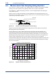
6.5 SwitchingMeasurementFlowPathUsing
Multi-Selector
Thisitemisanoption,soifyoudidnotspecifyoption“/MS,”thisfunctiondoesnotwork.
Whenoxygenconcentrationatmultiplelocationsismeasured,themulti-selectorallowsswitching
ofmeasurementowpathusingtherelaycontactoutput.Threegasowscanbeswitchedfromthe
panel.
SpecifytheowpathNo.(“1”through“3”)inthemaintenancemode“MLS.”Thedefaultin“MLS”is“0.”
For details, see Section 6.1.9, “Setting Multi-Selector “MLS”.” Furthermore, output of measurement
owpathdatacanbeperformedbycombiningtwocontacts.
MS1
MS2
MS3
MSI1
MSI2
MSICOM
MSCOM
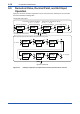
MSI1-MSICOM MSI2-MSICOM
MS OFF OPEN OPEN
MS1 (1st flow) CLOSE OPEN
MS2 (2nd flow) OPEN CLOSE
MS3 (3rd flow) CLOSE CLOSE
Solenoid valve
Contact output for switching of measurement
flow path
1st flow path
2nd flow path
3rd flow path
Power supply
OX400 terminal markings
Contact output to the customer
Output for measurement
flow path data. (Note)
(Note)
The following table shows the relationships of flow
no. contact signals. The flow set in “MLS” closes.
Figure6.20 SwitchingMeasurementFlowPathUsingMulti-Selector
(ExampleofThreeGasFlows)
Whenthemulti-selectorisused,theowpath“MLS1”through“MLS3”undermeasurementare
displayed on the sub-display on the front panel. If an error or alarm occurs while the multi-selector is
used,theowpathNo. anderror/alarmaredisplayedsequentially.