
Manual


<6.OperationandParameters>
6-2
IM 11M10B01-01E
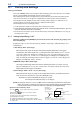
6.1 StartupandSettings
TurningonthePower
Turn on the POWER switch on the front panel. After all displays turn on, the warm-up screen “HEAt”
appears, and the OX400 automatically enters the warm-up mode.
The remaining warm-up time is displayed and counted down from 20, and when the warm-up time
ends, the measurement screen appears automatically. The warm-up time is about 20 minutes.
The mA output is 4 mA during the warm-up time, and the voltage output is 0 V. Furthermore, it is
recommended to check and set the parameters during the warm-up time.
The following shows the operating procedure.
1. Set the parameters required for operation (in the maintenance mode).
2.Checkandadjustthesamplegasowrate(200±25ml/min,aoatershouldbebetweenupperand
lowerbarofthe200ml/minbaronowmeter)
3. Check the measured values (in the measurement mode), and perform calibration, if necessary (in
the maintenance mode).
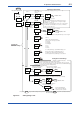
6.1.1 SettingOutputRange“rnG”
Operation:Holddownthe[MODE]keyfor2seconds,select“rnG”withthe[▲],[▼]keys,and
pressthe[ENT]key.
Roughly three types of measurement range are available, “Auto Range,” “MANUAL Range,” and
“Partial Range.”
1)AutoRange“AUto”(autorange)
Withrespecttothisrange,therangeisswitchedautomaticallydependingontheoxygen
concentrationvalue.Enterrangecode“1”(default)ifthefullscaleisalways10x10
n
, as in the
case of 0 to 10 ppm, 0 to 100 ppm, 0 to 1000 ppm, 0 to 10%, 0 to 100%. Furthermore, enter
range code () “2” to “9”, as in the case of 0 to 0 ppm, 0 to 00 ppm, 0 to 000 ppm, 0 to
0%.Forexample,enterrangecode“2”if20x10
n
applies, as in the case of 0 to 20 ppm, 0 to
200 ppm, 0 to 2000 ppm, 0 to 2%, 0 to 20%.
2) MANUAL
Range“MAn”(xed range)
Thisrangeisaxedrange.Selectonefromthefollowingsixranges:0to10ppm,0to100
ppm, 0 to 1000 ppm, 0 to 1%, 0 to 10%, and 0 to 100%. The range is always the same and is
independentfromtheoxygenconcentration.
3)PartialRange“FrEE”–“Fr.HI”–“Fr.Lo”(freerange)
Withrespecttothisrange,anyrangecanbesetandxed.However,thesmallestspanofthe
range must be more than 20%FS of the above MANUAL range.
Examples:2to4ppmiftheMANUALrangeis0to10ppm
60 to 80 ppm if the MANUAL range is 0 to 100 ppm
NOTE
: Flashing italic characters such as “1.000”usedinthesubsequentoperationowchartsmean
waitingforkeyinput.Furthermore,thelargerboxmeansthemaindisplay(largedigitaldisplay)
onthefrontpanelandthesmallerboxmeansthesub-display(smalldigitaldisplay).
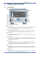
AUto
rnG
Main display
MODE LED
The MODE LED
turns on in the
maintenance mode.
The event of an error causes the LED to turn on.
The event of an alarm causes the LED to flash.
Sub-display
ERR/ALM LED
The respective unit turns on.
%
PPM
Unit LED
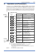
MODE
ERR/ALM
Operation in the maintenance mode
Press the key to return to the previous operation.
Hold down the key for 2 seconds to return to
the measurement mode.
You may need to enter a numerical value, decimal point,
and unit during the operation.
The following operation flow charts may omit this operation.
For details of the numerical value, decimal point, and unit operation,
see Section 6.6.
MODE
MODE