
Manual


<5.NamesandFunctions>
5-3
IM 11M10B01-01E
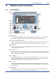
5.2 RearPanel
!
INLET
OUTLET
N200
C US
R
172608
SERIAL
(RS-232)
FUSE
250V T3.15A
!
RCCOM
RC3
RC2
RC1
FAIL
DO
PUMP
OFF
G
V
-
+
mA
-
+
MS1
MS2
MS3
MS
COM
MSI
COM
MSI2
MSI1
1
12
2
3
4
5
6
7
8
9
10
11
13
NOT using
Figure5.3DescriptionofRearPanel
1
Gas Inlet
Thisisaninletforintroducingsamplegas.TheconnectorisRc1/4or1/4NPT.
2
Gas Outlet
Thisisanoutletfordischargingsamplegas.TheconnectorisRc1/4or1/4NPT.
3
Fan
This is a cooling fan inside the OX400. Make sure the outlet of the fan is not blocked
4
Power Plug
This is a 3P power plug with a ground terminal. A fuse is included. Use the supplied power cord.
Do not use the power cord with another device.
5
Contact Output Terminal (DO Output)
Theeventofahighorlowoxygenconcentrationalarm“ALM7”causesoutputattheterminal.It
does not work without a concentration alarm.
6
Contact Output Terminal (FAIL)
This is a contact output terminal for errors. The event of an error causes output.
7
Contact Output Terminal for Range Output
In the auto range, the current range is output at the contact output terminal
8
Fuse Rating Display
The rating of the power fuse is displayed.
9
Contact Input Terminal
This contact input terminal is used to turn on and off the suction pump from the outside.
10
ExternalOutputTerminal(PrimaryOutput)
Measured values are output at 4-20 mA DC in the set measurement range.