
Manual


<4.PipingandWiring>
4-1
IM 11M10B01-01E
4. PipingandWiring
4.1 Piping
Be sure to observe the following precautions when connecting the gas pipe to the OX400.
1) TheconnectionsforboththegasinletandoutletareRc1/4or1/4NPT.Usethespeciedthread
and securely connect the gas pipe so that no leakage will occur.
WARNING
Whenscrewinginthepipe,besuretoholdtheinlethexagonalpartinplacewithawrenchorthelike.
Not doing so and using a strong force when screwing in the pipe may cause the thread on the OX400
to rotate, resulting in damage to the internal pipe.
2) With respect to piping, use a metal pipe. Use of materials such as plastic, vinyl, rubber, and
thelikemayresultininaccuratemeasurementsduetothetransmissionofoxygenfromtheair
and absorption onto the inside surface of the pipe. Particularly with respect to silicon tube, be
carefulbecauseduetoitslargeoxygentransmissionrate,accuratemeasurementscannotbe
performed in the low concentration range.
3) Be careful of leakage from the pipe because it may cause measurement errors. Particularly in
the low concentration range, take great care because even though the pressure inside the pipe
ispositive,oxygenmayowfromtheairduetodiffusion,resultinginalargeerror.
4) Fluctuations of back pressure at the pipe outlet may cause measurement errors, so always keep
the pressure at the atmosphere pressure level as much as possible during operation.
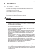
P
P
Flow meter
Suction pump
Heater
Oxygen
sensor
IN
OUT
IN
OUT
Oxygen
sensor
With aspirator (Sampling method [-A])
Built-in pump (Sampling method [-P])
Filter1
Filter2
Restriction
Filter1
Filter2
Aspirator
Sample gas
Sample gas
Pipe connection
Rc1/4 or
1/4NPT
Air or N
2
supply gas
inlet Φ6 connector
Φ8 connector
(Operable from
the front panel)
Note: If no suction device [-N] is specified, the aspirator is removed from this diagram.
Refer to sec. 6.4 when using aspirator.
Flow meter
Heater
Restriction
(Operable from
the front panel)
Throttle
valve
Throttle
valve
Figure4.1 PipingFlowDiagram