User’s Manual Model OX400 Low Concentration Zirconia Oxygen Analyzer [Style: S2] IM 11M10B01-01E R IM 11M10B01-01E 3rd Edition
INTRODUCTION n Safety, Protection, and Modification of the Product • In order to protect the system controlled by the product and the product itself and ensure safe operation, observe the safety precautions described in this user’s manual. We assume no liability for safety if users fail to observe these instructions when operating the product. • If this instrument is used in a manner not specified in this user’s manual, the protection provided by this instrument may be impaired.
ii n Notes on Hardware l Appearance and Accessories Check the following when you receive the product: • Appearance • Standard accessories Contact our sales representative or your local distributor if the product’s coating has come off, it has been damaged, or there is shortage of required accessories. l Model and Suffix Codes The name plate on the product contains the model and suffix codes.
iii • Display contents on the display Represented by “ ”. Example: Main display --> “HEAt” Example: Sub-display --> “CAL” Example: Data display --> “10.00” (in the ON state) Example LED lamp --> • PPM PPM (in the OFF state) Graphical representation of the flashing state Represented by italic characters or the Flashing state • (in the ON state), 1.000 mark. Flashing state of decimal point 1.
iv • When opening the cover to replace the sensor, turn off the power switch, remove the power plug from the socket, and wait for 1.5 hours or more before opening the cover. • Before connecting wires to the terminal block on the rear panel of the OX400, remove the power plug from the socket in order to prevent electric shock. After finishing the wiring, secure the removed special terminal cover with screws.
u After-sales Warranty n Do not modify the product. n During the warranty period, for repair under warranty carry or send the product to the local sales representative or service office. Yokogawa will replace or repair any damaged parts and return the product to you. Before returning a product for repair under warranty, provide us with the model name and serial number and a description of the problem. Any diagrams or data explaining the problem would also be appreciated.
vi IM 11M10B01-01E
Model OX400 Low Concentration Zirconia Oxygen Analyzer [Style: S2] IM 11M10B01-01E 3rd Edition CONTENTS INTRODUCTION........................................................................................................i u After-sales Warranty............................................................................................v 1. Outline........................................................................................................ 1-1 2. Specifications.................
ii 7. Setting Calibration Gas Concentration “SEt.C”.................................. 6-7 6.1.7 Setting Sensor Constant “SEnS”........................................................ 6-7 6.1.8 Setting Output Smoothing “SMoo”...................................................... 6-8 6.1.9 Setting Multi-Selector “MLS”............................................................... 6-8 6.1.10 Checking Calibration Coefficient “CoEF”............................................ 6-8 6.1.
1-1 <1. Outline> 1. Outline The OX400 is a highly accurate and reliable low concentration zirconia oxygen analyzer that is capable of measuring a wide range of concentrations, from 0-10 ppm up to 0-100 vol% O2. This is the latest oxygen analyzer from Yokogawa, and its development was based on the company’s long experience and strong track record with this technology.
1-2 IM 11M10B01-01E <1.
2-1 <2. Specifications> 2. Specifications 2.1 Standard Specifications Measurement object : Oxygen concentrations in inert gases containing no flammable gas, silica, corrosive gas, or liquid (including water vapor). Measurement system: Zirconia system Sampling method: Pump, aspirator, or no suction device. Pump and aspirator suction flow rate : Approx. 1.0 l/min. Aspirator suction conditions : Air or N2, supply pressure 65 to 100 kPaG, total discharge flow 10 l/min max.
2-2 <2. Specifications> Contact output: 3 outputs Error contact, O2 concentration high/low alarm contact, range marker output Multi selector (optional) : Contact output for switching sample gas flow, measument flow information contact output. Note : For details , see external dimensions.
2-3 <2.
2-4 <2. Specifications> Response time : 90% response : Within 10 sec (0-1% or more) : Within 30 sec (less than 0-1%) Drift : ±2% FS / week 2.
2-5 <2. Specifications> Consumables Part no. and rating Item Qt’y Activated filter element kit (15 times replacement) K9643KK 1 Filter kit (5 times replacement) K9643KL 1 Sensor assembly (including O-ring) K9643KG 1 Snap ring (retainer) Y9011EV 1 (*) Plate K9213FB 1 (*) Filter K9643FB 1 (*) Snap ring plier K9643ZE 1 (*) Qt’y of 10 pieces or more can be purchased. 2.
2-6 <2. Specifications> Panel mount type with aspirator (OX400--A--/P) 260 Unit: mm Mount 238 330 19.3 132 6 101.6 6 10 to 20 20 Frame 40 to 50 Frame (Line connection : in case of Rc1/4) Ventilation holes Screw 60 to 70 (Line connection : in case of 1/4NPT) 240 225 Bushing ±1 Seal 101.6 ±0.3 (Line connection : in case of Rc1/4) Connector Bushing (Line connection : in case of 1/4NPT) Aspirator 135 +2 0 Aspirator ±1 4xM5 screw Panel Cutout Notes on mounting 1.
2-7 <2. Specifications> Desktop type with built-in pump or no suction device (OX400----) Unit: mm Rear 35.3 With multi selector function 40 46 Sample gas inlet Sample gas outlet 10 to 20 350 19.3 20 132 213 Note: Pump ON/OFF switch; when no suction device [-N] is specified for the sampling method, this switch is not installed. Notes on installation Hot air is discharged from the air outlet on the rear panel of the OX400.
2-8 <2. Specifications> Desktop type with aspirator (OX400--A--) (Line connection : in case of Rc1/4) Aspirator Aspirator Bushing Bushing Unit: mm (Line connection : in case of 1/4NPT) Connector Sample gas inlet 35.3 Rear 40 46 With multi selector function 19.3 20 132 213 Aspirator gas inlet (Φ6) Aspirator and sample gas outlet (Φ8) 10 to 20 350 40 to 50 Notes on installation Hot air is discharged from the air outlet on the rear panel of the OX400.
2-9 <2. Specifications> Activated carbon filter Activated carbon filter of option code “/A” K9643KH: Rc1/4 K9643KJ: 1/4NPT Unit: mm Maintenance space The filter holder including piping connection can be more than 200 moved upward to replace 29.5 a filter element. 2-M5 screws Sample gas inlet (Rc1/4 or 1/4NPT) 110 ± 0.5 Mark “A” In case of K9643KJ 110 ± 0.5 150 (157) 130 Sample gas outlet (Rc1/4 or 1/4NPT) Fixing holes 2-Ф6.
2-10 <2. Specifications> 2.
<2. Specifications> 2.
2-12 IM 11M10B01-01E <2.
3-1 <3. Installation> 3. Installation 3.1 Installation Location The OX400 is a measuring instrument intended to be installed indoors. Install and operate it in a location that meets the following conditions in order to ensure the best performance. (1) Location where there is no corrosive gas. (2) Indoor location where there is no mechanical vibration. (3) Location that is not exposed to direct sunlight and radiant heat. (4) Location that is free of dust and dirt particles.
3-2 <3. Installation> 3.2 How to Install 3.2.1 Installing Desktop Type Place and operate the OX400 on a level surface as shown in Figure 3.1. (1) Provide a distance of 100 mm or more behind the OX400 in order to not block the outlet of the cooling fan on the rear panel. 2) The air inlet of the cooling fan is located on the bottom panel of the OX400. Be sure to provide a distance from the installation surface (desktop) larger than that of the height of the legs of the OX400.
3.2.2 3-3 <3. Installation> Installing Panel Mount Type (1) Attach a panel mount frame to the side of the OX400, insert it into the panel, and securely screw it to the panel. (2) Provide a distance of 100 mm or more behind the OX400 in order to not block the outlet of the cooling fan on the rear panel. (3) The air inlet of the cooling fan is located on the bottom panel of the OX400.
3-4 3.2.3 <3. Installation> Mounting Activated Carbon Filter Mount the filter on a panel or wall. To fix the filter with M5 screws. When replace a filter pack, 200 mm or more of maintenance space is necessary. If necessary, the piping connection should be removable. Activated carbon filter of option code “/A” K9643KH: Rc1/4 K9643KJ: 1/4NPT Unit: mm Maintenance space The filter holder including piping connection can be more than 200 moved upward to replace 29.5 a filter element.
<4. Piping and Wiring> 4. Piping and Wiring 4.1 Piping 4-1 Be sure to observe the following precautions when connecting the gas pipe to the OX400. 1) The connections for both the gas inlet and outlet are Rc1/4 or 1/4NPT. Use the specified thread and securely connect the gas pipe so that no leakage will occur. WARNING When screwing in the pipe, be sure to hold the inlet hexagonal part in place with a wrench or the like.
4-2 <4. Piping and Wiring> DO PUMP OFF MS1 FAIL ! RC1 MS3 + mA - - MS COM GG ++ RC3 MS2 MSI1 - INLET RC2 (The connection is Rc1/4 or 1/4NPT) RCCOM V - MSI2 ! MSI COM R C 172608 SERIAL (RS-232) Gas inlet OUTLET Gas outlet US N200 FUSE 250V T3.15A CAUTION For piping, use a metal pipe. Screw in the pipe while holding the hexagonal part with a wrench or the like.
4-3 <4.
4-4 <4. Piping and Wiring> 1) Primary output terminal This is a terminal to output oxygen concentration at a 4-20 mA DC current. Use it at a load resistance of 550Ω or less. The wire shall be shielded, and the shield shall be connected to the ground on the receive side and open on the OX400 side. 2) Secondary output terminal This is a terminal to output oxygen concentration in terms of voltage. Specify in advance one of 0-1, 0-5, and 0-10 V DC. Use it at a load resistance of 10 kΩ or more.
4-5 <4. Piping and Wiring> Table 4.3 Measurement Flow Path Switching Output by Multi-selector MS1-MSCOM MS2-MSCOM MS3-MSCOM MS OFF 0 0 0 MS1 ON (Select flow path 1) 1 0 0 MS2 ON (Select flow path 2) 0 1 0 MS3 ON (Select flow path 3) 0 0 1 • Output of information on flow path under measurement by multi-selector: Answer-back output of the flow path that is being measured. ”1” when lines between terminals MSI1/MSI2 and MSICOM are closed, and “0” when open. Table 4.
4-6 IM 11M10B01-01E <4.
5-1 <5. Names and Functions> 5. Names and Functions 5.1 Front Panel 1 2 6 5 3 4 11 9 8 7 12 10 Figure 5.1 Description of Front Panel 1 Main Display The main display digitally displays the oxygen concentration and set value in four digits with a decimal point. The display flashes at one-second intervals while waiting for key input. 2 Oxygen Concentration Unit LED The unit of displayed oxygen concentration is displayed by LED.
5-2 <5. Names and Functions> 8 Arrow Keys [◄], [►]: Press the keys to move through the digits of the number to be set. [▲], [▼]: Press the keys to scroll through the numbers or items to be set. SETTING/ENTER Key 9 Press the key to confirm the item or number to be set. Press [ENT] to display the operation description. 10 Gas Flow Rate Adjustment Knob Use the knob to adjust the gas flow rate of gas flowing into the sensor. PUMP Switch 11 Turn the switch on to use the built-in pump.
5-3 <5. Names and Functions> 5.2 Rear Panel 3 9 5 DO PUMP OFF NOT using 10 MS1 FAIL MS3 RC1 INLET 7 RC2 G MS COM RC3 + V - MSI1 12 1 ! + mA - MS2 11 6 2 RCCOM MSI2 OUTLET ! MSI COM R C SERIAL (RS-232) 172608 13 US N200 FUSE 250V T3.15A 8 4 Figure 5.3 Description of Rear Panel 1 Gas Inlet This is an inlet for introducing sample gas. The connector is Rc1/4 or 1/4NPT. 2 Gas Outlet This is an outlet for discharging sample gas. The connector is Rc1/4 or 1/4NPT.
5-4 <5. Names and Functions> 11 External Output Terminal (Secondary Output) Measured values are output at the set voltage (0-1, 0-5, and 0-10 V DC) 12 Multi-Selector Contact Output Terminal This is the contact output to switch measurement flow path. Furthermore, measurement flow path data is output at this contact output terminal. 13 RS232 Connector A D-sub 9-pin connector is connected to this connector when using serial communication.
6-1 <6. Operation and Parameters> 6. Operation and Parameters The OX400 has two modes, “Measurement Mode” and “Maintenance Mode.” Oxygen concentration is displayed in the measurement mode. The setting of operation parameters and calibration operation are performed in the maintenance mode. Furthermore, the MODE LED on the front panel is on in the maintenance mode. To enter the maintenance mode, or to return to the measurement mode from the maintenance mode, hold down the [MODE] key for two seconds.
6-2 <6. Operation and Parameters> 6.1 Startup and Settings Turning on the Power Turn on the POWER switch on the front panel. After all displays turn on, the warm-up screen “HEAt” appears, and the OX400 automatically enters the warm-up mode. The remaining warm-up time is displayed and counted down from 20, and when the warm-up time ends, the measurement screen appears automatically. The warm-up time is about 20 minutes. The mA output is 4 mA during the warm-up time, and the voltage output is 0 V.
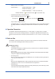
6-3 <6. Operation and Parameters> MODE Hold down for 2 seconds. (Note 1) To “rEV” AUto ▼↓↑▲ ▼ ▲ To 100% rnG [ENT] rnG MANUAL Range (Note 2) 10 00 % PPM MAn ▼↓↑▲ 10 0 0 % PPM [ENT] Range of 0 to 100 ppm is confirmed % 100 0 PPM (Note 2) How to set the manual fixed range Select one of the six ranges as follows: 0 to 10 ppm, 0 to 100 ppm, 0 to 1000 ppm, 0 to 1%, 0 to 10%, 0 to 100%. % PPM MAn ▲ ▼↓↑▲ 10 00 Return to “rnG.
6-4 6.1.2 <6. Operation and Parameters> Setting Secondary Output “oUt2” Operation: Hold down the [MODE] key for 2 seconds, select “oUt2” with the [▲], [▼] keys, and press the [ENT] key. With respect to the secondary output, select one of the three types of voltage output: 0-1 V is “1,” 0-5 V is “5,” and 0-10 V DC is “10.” Figure 6.3 shows an example of setting 0-1 V DC “1.” To “rEV” ▼↓↑▲ MODE Hold down for 2 seconds. CAL ▼↓↑▲ rnG To “10” oUt2 0-1 V DC is confirmed.
<6. Operation and Parameters> 6.1.4 6-5 Setting Burnout Function “nAMU” Operation: Hold down the [MODE] key for 2 seconds, select “nAMU” with the [▲], [▼] keys, and press the [ENT] key. Set the burnout function for the primary current output of 4-20 mA DC (compliant with NAMUR). Select one of the options: No burnout function is “non,” burn-up is “Er.HI,” and burn-down is “Er.Lo.” Figure 6.5 shows an example of setting burn-up.
6-6 6.1.5 <6. Operation and Parameters> Setting Alarms (Oxygen Concentration High/Low Alarms) “ALM” Operation: Hold down the [MODE] key for 2 seconds, select “ALM” with the [▲], [▼] keys, and press the [ENT] key. High and low limit alarms can be set to the measured oxygen concentration values. With respect to the alarm setting, the following four options are available: No alarm “oFF,” high/low limits “ALL,” high limit alarm “AL.HI,” and low limit alarm “AL.Lo.
6-7 <6. Operation and Parameters> 6.1.6 Setting Calibration Gas Concentration “SEt.C” Operation: Hold down the [MODE] key for 2 seconds, select “SEt.C” with the [▲], [▼] keys, and press the [ENT] key. Set the O2 concentration of gas used for calibration. Alternatively, this setting can be performed while performing calibration “CAL.” The gas concentration that can be set is restricted depending on which calibration is performed (which depends on the specification in calibration “CAL”).
6-8 6.1.8 <6. Operation and Parameters> Setting Output Smoothing “SMoo” If the oxygen concentration of sample gas rapidly changes, and the measured value is used for control, harmful results may occur such as frequent on and off switching. In such a case, signal changes can be smoothed by giving an appropriate time constant and performing calculation. Smoothing factor from 0 to 60 seconds can be set.
<6. Operation and Parameters> 6-9 and press the [ENT] key. Check the current calibration coefficient. These coefficients are updated for each calibration. Figure 6.11 shows an example of checking the coefficient. To “rEV” ▼↓↑▲ CAL MODE Hold down for 2 seconds. ▼↓↑▲ ▼↓↑▲ CoEF [ENT] % 1. 011 PPM [ENT] % 1. 013 PPM [ENT] 1. 35 % PPM [ENT] dZ4 dS4 Figure 6.11 % PPM [ENT] dZ1 dS1 ▼↓↑▲ - 0. 23 Return to “CoEF.” Checking Calibration Coefficient “CoEF” 6.1.
6-10 <6. Operation and Parameters> To “rEV” ▼↓↑▲ MODE Hold down for 2 seconds. CAL ▼↓↑▲ ▼↓↑▲ rEV [ENT] ▼↓↑▲ 6.2 Figure 6.13 1. 8 % PPM [ENT] Return to “rEV.” rEV Display Software Revision “rEV” Calibration “CAL” Be sure to perform calibration in the measurement mode after the warm-up operation ends. Calibration cannot be performed during the warm-up operation. If an error occurs during calibration, that calibration will be invalid, and keys other than the [MODE] key become invalid.
6-11 <6. Operation and Parameters> calibration. However, there are the following limits to the O2 concentration. Be sure to perform calibration in that range of the O2 concentration. O2 concentration limits: 0.9 ppm or more and 12% or less, or between 35% and 100%. 4) Air calibration “AIR” This is air-only calibration. Ues the cleanest air possible to perform calibration. NOTE: If you press the [MODE] key during calibration to exit the calibration mode, that calibration becomes invalid.
6-12 <6. Operation and Parameters> 6.3 Communication The OX400 has RS232 serial communication as standard. Oxygen concentration, alarm, and error information are transmitted via this communication. The following shows the communication specifications. • Communication Specifications Table 6.
<6. Operation and Parameters> Table 6.3 6-13 Error Factor and Output Character List Output characters Error factor 0001 Err1: Sensor error 0002 Err2: Heater temperature error 0004 Err3: Temperature sensor burnout 0008 Err4: Device temperature error 0010 Err5: CPU error 0020 Err6: FAN stop If multiple errors occur, the logical sum of output characters is output. Example 1 : 0003; Err1 and Err2 are occurring Example 2 : 0017; The four errors Err1, Err2, Err3, and Err5 are occurring.
6-14 <6. Operation and Parameters> 6.4 Measurement Gas Sampling Using Aspirator If you selected “-A”: with an aspirator as the sampling method, an aspirator is included in the OX400 package. Connect the aspirator to the sample gas outlet on the rear panel of the OX400. If you selected “T”: 1/4NPT as the piping connector, connect an adapter between the sample gas outlet and the aspirator. Supply clean air or N2 gas to the aspirator.
6-15 <6. Operation and Parameters> 6.5 Switching Measurement Flow Path Using Multi-Selector This item is an option, so if you did not specify option “/MS,” this function does not work. When oxygen concentration at multiple locations is measured, the multi-selector allows switching of measurement flow path using the relay contact output. Three gas flows can be switched from the panel. Specify the flow path No. (“1” through “3”) in the maintenance mode “MLS.” The default in “MLS” is “0.
6-16 <6. Operation and Parameters> 6.6 Numerical Value, Decimal Point, and Unit Input Operation Figure 6.21 shows an example of operation to input a numerical value, decimal point, and unit. Italic characters indicate the flashing state. Numerical value input Increment by pressing the ▲key. (0→1→ • • • →9→0) The 4th digit flashes. The 3rd digit flashes. % % 10.00 PPM ZEro 10.00 PPM ZEro 10.0 0 PPM ZEro [ENT] Decimal point and unit input Decrement by pressing the ▼ key.
7. 7-1 <7. Inspection and Maintenance> Inspection and Maintenance Routine inspection and maintenance is important to ensure operation of the OX400 in a good condition. Perform regular inspection and maintenance in accordance with the following instructions. 7.1 Routine Inspection and Maintenance 1) Checking readings Measure calibration gas about once every two to three months and check the readings.
7-2 7.2.1 <7. Inspection and Maintenance> Inspection in the Event of an Alarm (ALM) If an error is detected by the self-diagnosis function of the OX400 during operation, the ERR/ALM lamp flashes and an alarm (ALM) code is displayed on the sub-display. If an error is detected, take action according to the Table 7.1. Table 7.
7-3 <7. Inspection and Maintenance> Note) If an error (ERR) occurs, the heater is turned off. To clear the error, you need to turn the power off and then on. It is recommended to turn the power off and then on to see whether the error occurs again. Be careful because if the power of the OX400 is turned off, the contact output “OPEN.” 7.3 How to Replace Sensor When the sensor has deteriorated, replace it with a new sensor. As for the part number, see CMPL at the end of this manual.
7-4 <7. Inspection and Maintenance> 5) Remove the lead wire connector of the sensor from the PCB board. 6) Loosen the joint ring 7) Pull out the joint 8) Rotate the inlet-side joint nut 2 1 on the sensor outlet side and remove it towards the heater side. while holding the sensor. 3 counter clockwise seen from the heater side and remove it. Lead wire connector 3 Sensor 1 2 Heater Lead wire connector 3 1 2 Heater O-ring 9) Pull out the holding plate straightforward.
7.3.2 7-5 <7. Inspection and Maintenance> Installing Sensor 1) Pass a new sensor through the heater. Lead wire connector Sensor Heater 2) Insert the nut 3 , holder 5 , and O-ring 6 in this order from the front end of the sensor. At this point, set the O-ring in the position about 3 mm from the sensor front end (It is recommended to replace the O-ring with a new one). Lead wire connector 5 3 13 mm Heater 6 3) O-ring Approx.
7-6 <7. Inspection and Maintenance> 4) Insert the ring 1 and holding plate 4 in this order into the sensor. Hold the sensor with fingers and rotate the joint 2 right and left to push it into the sensor slowly. Lead wire connector Sensor 3 4 1 2 Heater 5) Rotate and tighten the ring (7). 1 into the joint 2 . Secure the holding plate 4 with two screws Connect the lead wire connector of the sensor to the PCB board.
7-7 <7. Inspection and Maintenance> (1) Loosen the four screws with washers (2) Remove cotton filter C , felt filter (3) Dispose of activated carbon F D B of holder , and O-ring A E A and remove holder . (Figure 7.4) . . Remove the bottom side holder same as the upper side holder and pull out the activated carbon. Referring item (5) to (7), set the bottom side holder.
7-8 <7. Inspection and Maintenance> 7.5 How to Replace the Line Filter The line filter is inside the gas inlet connector on the rear panel. The line filter is covered by a plate, and both these parts are held in place by a C-shaped snap ring. The following explains how to replace the line filter. This requires a pair of snap ring pliers and some tweezers. 1) Insert the tips of the snap ring pliers in the holes on the snap ring and apply pressure to release and remove the snap ring.
“1” / “5” / “10” “non” / “PrEV” “0 to 60” “0” / “1” / “2” / “3” “HoLd” “nAMU” “ALM” “SEt.C” “SMoo” “MLS” Hold function Burnout function O2 conc. Hi/Low alarm Calibration gas concentration Output smoothing Multi-selector “1000” “10” Flow path No.1 to 3 “0” 0 sec Non use Non (Note 7) (Note 6) 1000 ppm gas conc. 1000 ppm Smoothing factor. (Note 5) (Note 4) 10.00 ppm 10 ppm gas conc. 3 points 1000 ppm Span-gas conc. “SPAn” (Note 3) 6.1.9 6.1.8 6.1.
8-2 IM 11M10B01-01E <8.
Customer Maintenance Parts List OX400 Low Concentration Zirconia Oxygen Analyzer [Style: S2] Aspirator (Rc1/4) Aspirator (1/4NPT) 1 2 Panel Mounting Hardware 3 Sensor related parts MS1 MS2 MS3 MS COM MSI1 8 (internal) DO PUMP OFF FAIL ! + mA - INLET RC1 RC2 G RC3 + V - RCCOM MSI2 OUTLET ! MSI COM R C 172608 SERIAL (RS-232) US N200 FUSE 250V T3.15A Heater 7 Item 1 Part No.
Activated Carbon Filter (Option code "/A") 2 Cotton filter 1 Felt filter 3 Item 1 Part No. K9643KH K9643KJ Qty 1 1 Description Filter Assembly (Rc1/4) Filter Assembly (1/4NPT) 2 3 K9643KK K9643KL 1 1 Activated Carbon Filter Element Kit (15 times replacement) Filter Kit (5 times replacement) CMPL 11M10B01-02E 2nd Edition : Apr.
Revision Information Title : Model OX400 Low Concentration Zirconia Oxygen Analyzer [Style: S2] Manual No. : IM 11M10B01-01E May.
Blank Page