
Instruction Manual


4
IM 77J08R05-01E 1st Edition 2007.01.15-00
5. LIST OF PARAMETERS
Parameter Display Items
A DISPLAY Display
A01 INPUT Input value
A02 OUTPUT Output value
A03 STATUS Status (*1)
A04 REV NO Revision number
B SET Setting
B01 TAG NO.1 Tag number 1
B02 TAG NO.2 Tag number 2
B03 COMMENT1 Comment 1
B04 COMMENT2 Comment 2
B05 TYPE Input type
B09 UNIT Unit
B10 ZERO Zero (0% of input range)
B11 SPAN Span (Input span)
B12 BURN OUT Burnout
C ADJUST Adjustment
C01 OUT 0% Output 0% adjustment
C02 OUT 100% Output 100% adjustment
C04 ZERO ADJ Input zero adjustment
C05 SPAN ADJ Input span adjustment
*1: This “STATUS” is for the customer’s engineer to check the history.
6. MAINTENANCE
The product starts running immediately when the power is turned
on; however, it needs 10 to 15 minutes of warm-up before it
meets the specied performance.
6.1 Calibration Apparatus
A 6-dial variable resistor (Yokogawa Meters & Instruments
Corporation 279301 or equivalent)
A digital multimeter (Yokogawa 7561 or equivalent)
A precision resistor of 250 Ω
±
0.01%, 1W
A setting tool for adjustment (Refer to "4. Setting Parameters"
in this manual.
6.2 Calibration Procedure
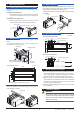
1. Connect the instruments as shown below.
1
2 3
4 5
6 7
3
2
6
7
4
5
1
A
B
B
6-dial
variable resistor
Setting tool
Output
Input
24V DC
Ro
Ro: 250Ω precision resistor for
current output
DMM
Power Supply
2 Use the 6-dial variable resistor and apply the resistance
equivalent to 0, 25, 50, 75, and 100% of the measuring range
to the converter.
3. Verify that the corresponding output voltages are 0, 25, 50, 75,
and 100% respectively and within the specied accuracy rating.
(R
o
is used for current output.)
Use the setting tool (VJ77 Parameter Setting Tool or JHT200
Handy Terminal) to adjust the input/output signals.
Input Adjustment Procedure
(1) Input the value equivalent to 0% value of the input range
to the converter.
(2) Read the parameter [C04: ZERO ADJ] and check the
input value.
(3) Select “INC” or “DEC” in the parameter [C04: ZERO
ADJ] to adjust.
INC: Increase (Adjusts the increased value of the input
[resistance] value)
DEC: Decrease (Adjusts the decreased value of the
input [resistance] value)
RST: Reset of the adjustment value
(4) Input the value equivalent to 100% value of the input
range to the converter.
(5) Read the parameter [C05: SPAN ADJ] and check the
input value.
(6) Adjust the span in the same way as (3).
Output Adjustment Procedure
When adjusting 0% value of output:
(1) Set the adjustment value 0% in the parameter [C01:
OUT 0%].
•The value equivalent to 0% of the output range will be
output, irrespective of the input.
(2) Check the output value via digital multimeter, and adjust
it in the parameter [C01: OUT 0%].
•If it slips out to the (+) side, set (−) value equivalent
to slipout; if it slips out to the (−) side, set (+) value
equivalent to slipout for adjusting the output value to
0%.
*: The 100% value of output can be adjusted by the
same operation as the above in [C02:OUT100%]
For adjustment using a setting tool, refer to the User’s Manual for
each setting tool and “5. List of Parameters” in this manual.
User’s Manual for VJ77 [Document No.: IM 77J01J77-01E];
however, use the VJ77 of version R1.05 or later.
User’s Manual for JHT200 [Document No.: IM JF81-02E]